the12volt.com spacer
icon

Viper 211HV and Bulldog RS82B in 01 F-150 SuperCrew


Post ReplyPost New Topic
< Prev Topic Next Topic >
rlwolfgram 
Member - Posts: 10
Member spacespace
Joined: November 07, 2013
Posted: August 02, 2018 at 2:06 PM / IP Logged Link to Post Post Reply Quote rlwolfgram
What I have:
- 2001 Ford F150 SuperCrew truck
- Viper 211HV keyless entry kit
- Bulldog Security RS82B remote start kit
What I want to do:
- Install Viper 211HV in my truck, utilizing the 211HV's progressive unlock option
- Install Bulldog RS82B, but trigger it using the 211HV's AUX button
What I know:
- I have successfully installed keyless entry systems and remote start systems, so I understand the "idiot" lingo from do-it-yourself install manuals. The Viper series "require" professional installation, so I feel I am missing some info.
- Per the dealer, my vehicle does not have factory keyless entry, so (per Bulldog Security) my lock system is "Type C" reverse polarity.
- I think there is a typo in the 211HV install manual. I'm not sure how much this is screwing my understanding up, but if it isn't a typo, I am completely lost. I believe the H1/6 line on page 4 should be 87A, not 87
- I found a wiring diagram for "Type C" reverse polarity locks on Bulldog's website, and I assume the relay numbers (30, 85, 86, 87, & 87A) are what the 211HV's H1/5, H1/6, H1/7, H1/8, H1/9, & H1/17 are referring to, but not all the relay pins are listed
- 211HV's H1/2 refers to the second lock output, which in the progressive lock system would be the second button press to unlock the rest of the doors
What I need help with:
- Just the progressive lock system. I have everything else color-matched to my vehicle's wiring. I don't know where to begin. Oddly I feel getting the RS82B to work off of the 211HV AUX button should be the hard part, but I have that figured out.
Links:
- Viper 211HV install manual
- F150 wiring colors
- RS82B manual
- "Type C" reverse polarity locks relay diagram
kreg357 
Platinum - Posts: 7,783
Platinum spaceThis member has made a donation to the12volt.com. Click here for more info.spaceThis member has been recognized as an authority in Electrical Theory. Click here for more info.spaceThis member has been recognized as an authority in Mobile Security and Convenience. Click here for more info.spacespace
Joined: January 30, 2009
Location: Pennsylvania, United States
Posted: August 03, 2018 at 8:49 AM / IP Logged Link to Post Post Reply Quote kreg357
Well, it looks like you are doing your research and almost finished.
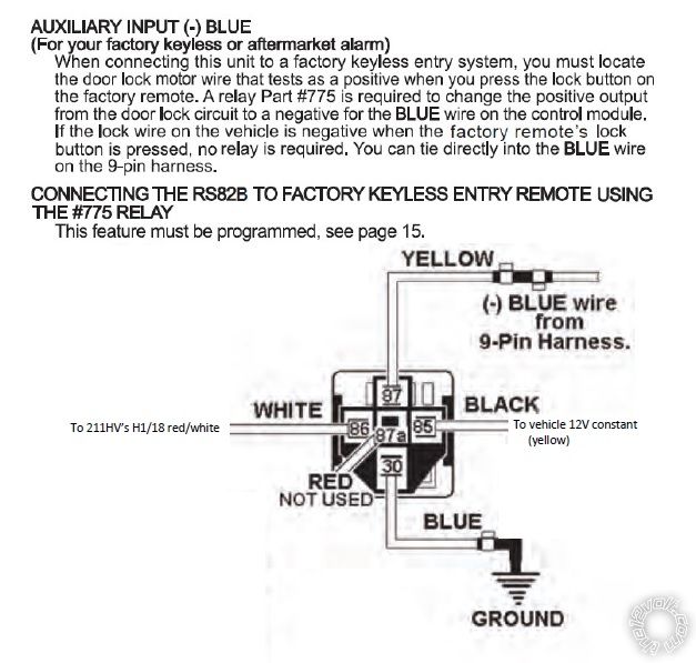
Yes indeed, the 211HV manual is wrong. The H1/6 wire is actually Pin 87A of the internal Lock relay.
Using the 211HV's H1/14 WHITE/BLUE (-) 200 mA CHANNEL 3 Trunk output to trigger the RS82B's R/S Blue trigger wire is a
somewhat hidden feature that requires a programming change on the R/S. Good work there.
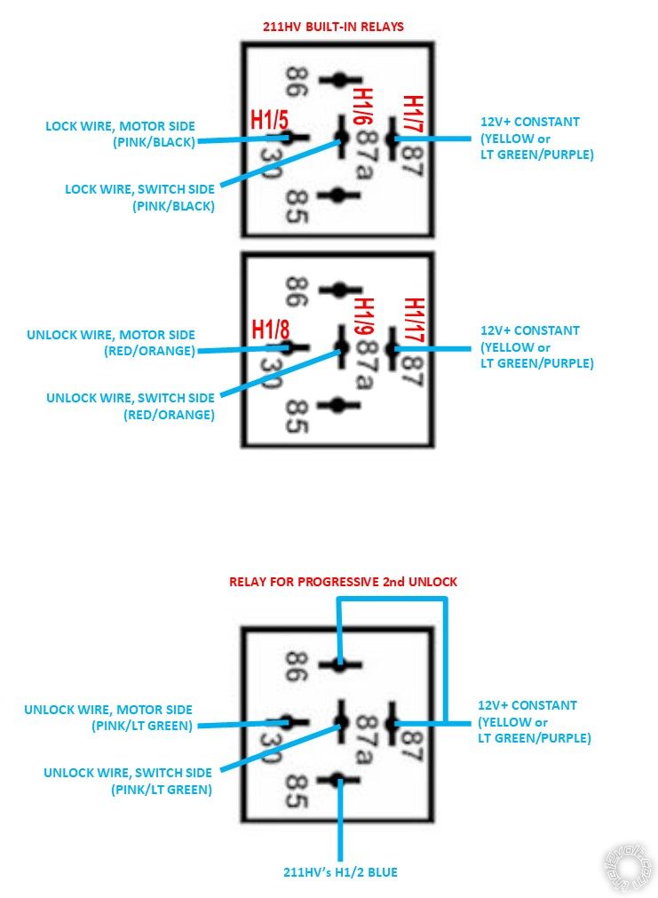
Getting Progressive Unlock will require a bit more work and an additional external relay. Being as you don't have Factory Keyless
Entry, you don't have the GEM module and must wire into the lock system via the Type C method. Not a big deal with the 211HV
as it has internal relays. The twist is using the 211HV's Blue Second Unlock wire. So, for wiring, you would connect the 211HV
Lock outputs in the Type C fashion to the trucks Pink/Yellow. I usually go to the passanger side kick panel for these wires
because of easier access. The 211`HV's Unlock wires would go to the wire shown below :
Motor Driver Unlock      RED/ORANGE   AT OEM RELAYS OR DRIVER KICK PANEL *
This wire unlocks only the Drivers Door. And finally the HV211's Blue Second Unlock wire controls an external 30/40 Amp SPDT
relay to the Pink/Light Green Unlock ALL wire. The Second Unlock output would unlock all the doors on the 211HV's second
unlock buttom depression.
External Relay wires :
Relay Pin 85 to 211HV Blue Second Unlock
Relay Pins 86 and 87 to +12V through 20 Amp fuse
Relay Pin 87a to non-motor side of cut Pink/Light Green Unlock wire
Relay Pin 30 to motor side of cut Pink/Light Green Unlock wire
* This info is from Omega and not personally verified by me. Additionally they list other color wires for the Lock and Unlock wires
    as noted below so testing is important :
Motor Lock   PINK/BLACK   AT OEM RELAYS OR DRIVER KICK PANEL   
Motor All Unlock   PINK/ORANGE   AT OEM RELAYS OR PASS. KICK PANEL   
Motor Driver Unlock     (disarm defeat)   RED/ORANGE   AT OEM RELAYS OR DRIVER KICK PANEL
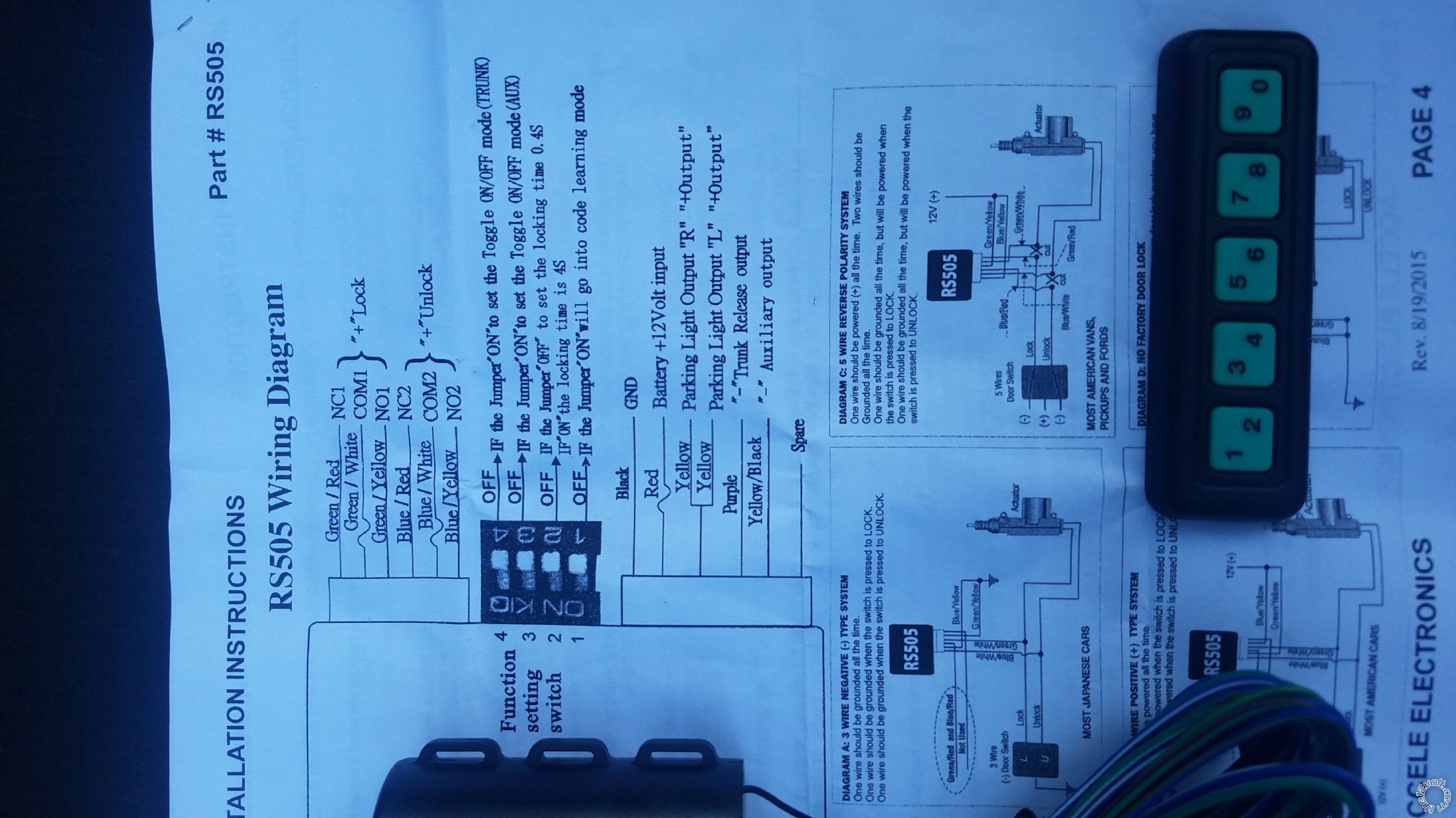
Here is a link to a very good guide on vehicle door lock types, testing and wiring :
https://www.the12volt.com/installbay/file.asp?ID=708
Some photos of the lock wires, etc, can be found in this Pictorial on your truck :
https://www.the12volt.com/installbay/forum_posts.asp?tid=134275
Soldering is fun!
rlwolfgram 
Member - Posts: 10
Member spacespace
Joined: November 07, 2013
Posted: August 03, 2018 at 12:06 PM / IP Logged Link to Post Post Reply Quote rlwolfgram
AWESOME! THANKS!
But you made me second guess the AUX on the 211HV. From the install manual of the RS82B, I altered the relay wiring diagram -- did I get it right?
Viper 211HV and Bulldog RS82B in 01 F-150 SuperCrew -- posted image.
kreg357 
Platinum - Posts: 7,783
Platinum spaceThis member has made a donation to the12volt.com. Click here for more info.spaceThis member has been recognized as an authority in Electrical Theory. Click here for more info.spaceThis member has been recognized as an authority in Mobile Security and Convenience. Click here for more info.spacespace
Joined: January 30, 2009
Location: Pennsylvania, United States
Posted: August 03, 2018 at 12:57 PM / IP Logged Link to Post Post Reply Quote kreg357
Looks like I was slightly wrong with the 211HV's correct Trunk Release Output wire. It is indeed the Red/White wire
at H1/18. And yes your relay diagram will work but...
Standard relay convention has the relay coil Pin 85 getting the (-) input signal and Pin 86 getting the (+) input signal.
Reversing them as shown on your diagram usually will not cause any problems unless the relay has a built in coil
quenching diode. In that case the Pin 85 and 86 polarity must be observed. Also note the last two sentences in the R/S
wire description. The relays purpose is to change the typical (+) Lock pulse to a (-) signal that the Blue wire needs
to initiate a R/S sequence. While you are not using a vehicle Lock wire as the input signal, the 211HV Trunk Release
output is a (-) signal that the R/S system is looking for. It should function properly without the relay, just a direct
connection.
Soldering is fun!
rlwolfgram 
Member - Posts: 10
Member spacespace
Joined: November 07, 2013
Posted: August 03, 2018 at 1:18 PM / IP Logged Link to Post Post Reply Quote rlwolfgram
Would I assume on the cut lock wires -- the half going towards the door is the motor side of the wire?
Do I understand this correctly:
Viper 211HV and Bulldog RS82B in 01 F-150 SuperCrew -- posted image.
rlwolfgram 
Member - Posts: 10
Member spacespace
Joined: November 07, 2013
Posted: August 03, 2018 at 1:23 PM / IP Logged Link to Post Post Reply Quote rlwolfgram
Sorry I'm jumping around...
In your response to the RS82B relay...I assumed with it only being a 200mA source that it needed a relay to juice up the power to the RS82B blue wire. I would prefer to use the least number of relays, so then I'll connect the 211HV's H1/18 red/white wire directly to the RS82B's blue wire. Thanks!
kreg357 
Platinum - Posts: 7,783
Platinum spaceThis member has made a donation to the12volt.com. Click here for more info.spaceThis member has been recognized as an authority in Electrical Theory. Click here for more info.spaceThis member has been recognized as an authority in Mobile Security and Convenience. Click here for more info.spacespace
Joined: January 30, 2009
Location: Pennsylvania, United States
Posted: August 03, 2018 at 1:28 PM / IP Logged Link to Post Post Reply Quote kreg357
The lock relay wiring is correct. Here is one way to determine the Motor or Switch side of the cut Type C lock wire :
Easy way to tell which side of the cut wire is the switch
and which is the motor, is to cut the wire and then press
the button. If it shows 12v it is the switch side of the
button you just pressed. Sometimes it isn't always easy
to tell which end goes to the switch and which side goes
to the car.
Remember to fuse the external relay's +12V supply power.
Soldering is fun!
kreg357 
Platinum - Posts: 7,783
Platinum spaceThis member has made a donation to the12volt.com. Click here for more info.spaceThis member has been recognized as an authority in Electrical Theory. Click here for more info.spaceThis member has been recognized as an authority in Mobile Security and Convenience. Click here for more info.spacespace
Joined: January 30, 2009
Location: Pennsylvania, United States
Posted: August 03, 2018 at 1:33 PM / IP Logged Link to Post Post Reply Quote kreg357
You are correct that adding a relay to the Trunk Release output will give it a better/stronger signal than the 211HV's 200mA output
and depending on the RS82B's needs might be required but I believe the un-enhanced 200mA signal should be sufficient.
Soldering is fun!
rlwolfgram 
Member - Posts: 10
Member spacespace
Joined: November 07, 2013
Posted: August 03, 2018 at 1:37 PM / IP Logged Link to Post Post Reply Quote rlwolfgram
Thanks again!
rlwolfgram 
Member - Posts: 10
Member spacespace
Joined: November 07, 2013
Posted: August 04, 2018 at 5:10 AM / IP Logged Link to Post Post Reply Quote rlwolfgram
I totally forgot I had this. It's a aftermarket door keypad like Ford's factory keypad. I bought it for a different vehicle I no longer have and found it when I was looking for a relay in a spare parts both.
If I wanted to throw this into the mix....the lock/unlock are relay connections just like the 211HV, right? Common is 87, normally closed is 87A, & normally open is 30?
Viper 211HV and Bulldog RS82B in 01 F-150 SuperCrew -- posted image.
Page of 2

  Printable version Printable version Post ReplyPost New Topic
You cannot post new topics in this forum
You cannot reply to topics in this forum
You cannot delete your posts in this forum
You cannot edit your posts in this forum
You cannot create polls in this forum
You cannot vote in polls in this forum

  •  
Search the12volt.com
Follow the12volt.com Follow the12volt.com on Facebook
Tuesday, April 16, 2024 • Copyright © 1999-2024 the12volt.com, All Rights Reserved Privacy Policy & Use of Cookies
Disclaimer: *All information on this site ( the12volt.com ) is provided "as is" without any warranty of any kind, either expressed or implied, including but not limited to fitness for a particular use. Any user assumes the entire risk as to the accuracy and use of this information. Please verify all wire colors and diagrams before applying any information.

Secured by Sectigo
the12volt.com spacer
Support the12volt.com
Top
the12volt.com spacer