the12volt.com spacer
icon

2002 Lexus SC430, Viper 5906v


Post ReplyPost New Topic
< Prev Topic Next Topic >
troybyfield 
Member - Posts: 4
Member spacespace
Joined: February 12, 2020
Location: Colorado, United States
Posted: February 21, 2020 at 10:10 PM / IP Logged Link to Post Post Reply Quote troybyfield
Seeking assistance/guidance with a remote start setup on a 2002 Lexus SC430. I am using the Viper 5906v with iDataLink ALCA. The iDataLink ALCA has been flashed with DBI-AL(TB)-TL (3.3)
Nothing is currently setup but this is what I am thinking about. Please let me know what needs to be corrected and/or any additions or recommendations. Thanks 2002 Lexus SC430, Viper 5906v -- posted image.
kreg357 
Platinum - Posts: 7,783
Platinum spaceThis member has made a donation to the12volt.com. Click here for more info.spaceThis member has been recognized as an authority in Electrical Theory. Click here for more info.spaceThis member has been recognized as an authority in Mobile Security and Convenience. Click here for more info.spacespace
Joined: January 30, 2009
Location: Pennsylvania, United States
Posted: February 22, 2020 at 4:58 AM / IP Logged Link to Post Post Reply Quote kreg357
Nice car, congratulations!   Mine is still going strong with 133,000 miles. No issues with the 4704 Viper after 8 years of use.
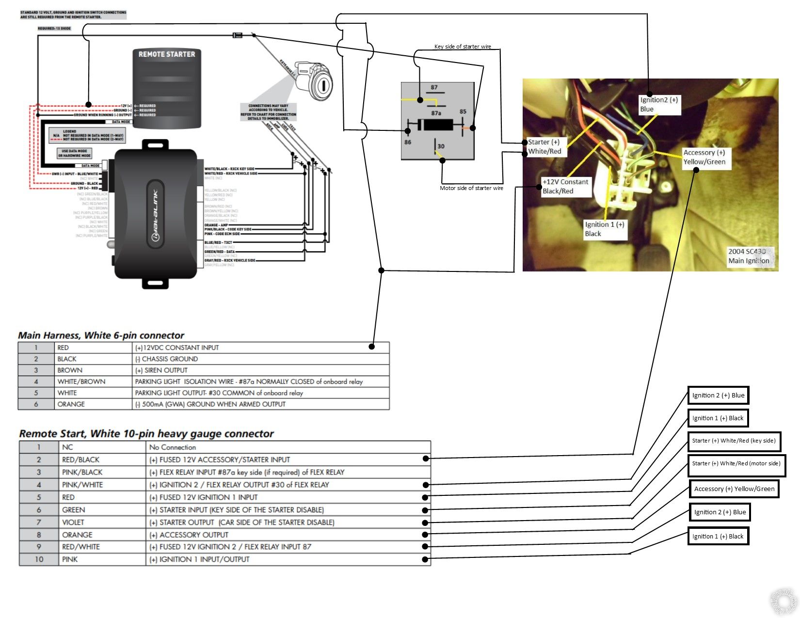
The iDatalink bypass module is a nice choice and with the DBI firmware can go D2D with the Viper 5906. The Red dashed lines in the Type 1 Install diagram are not necessary when running with D2D. Just make sure you set the ADS AL-CA to Data Mode ( one blink ) and lock it in when you start bypass module programming. This is shown at the top of Page 22.
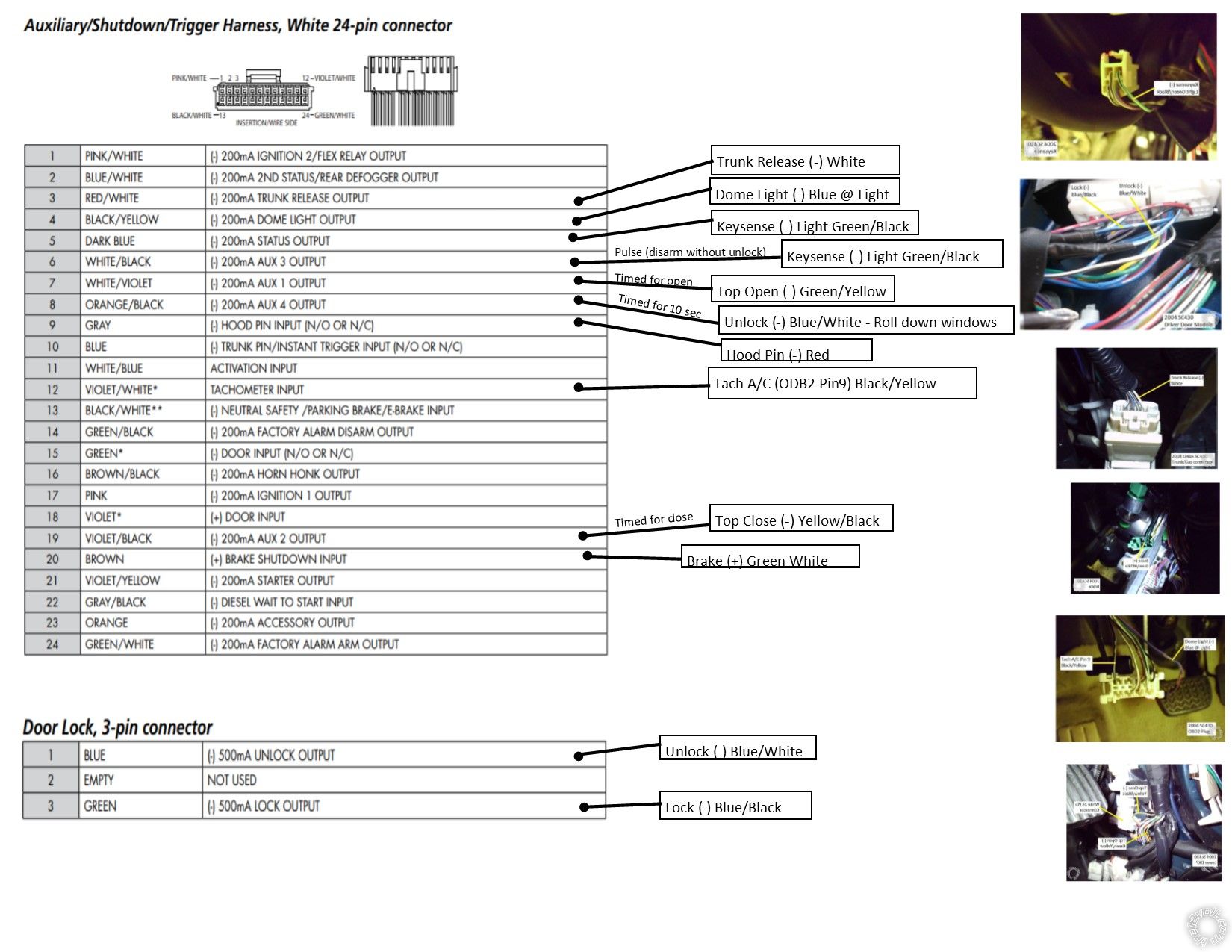
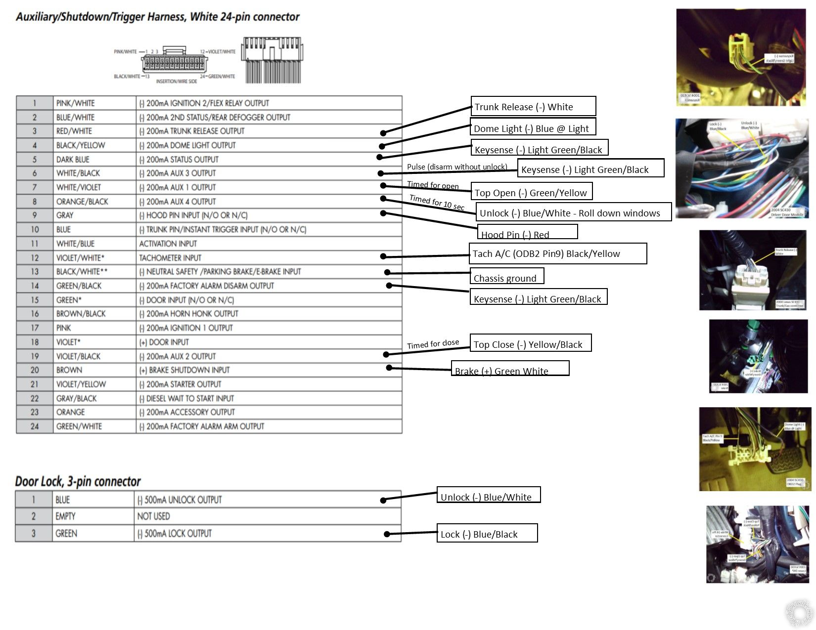
The good news is that the Viper has a built-in relay for Starter Kill and Anti-Grind so the relay you added in your posted diagram is not necessary. Just follow the Type 1 diagram for the bypass side of things. You can use either the Dark Blue (-) Status Output or the Blue/White (-) 2nd Status Ouput wire ( if you aren't planning on using it for the Defrost function ) for Keysense.
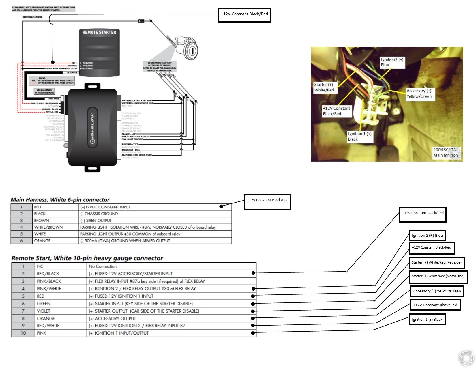
On the Viper wiring, a basic rule of thumb is any wire that includes a fuse is a +12V Constant Input wire. So the Red wire at the 6 Pin plug and the three fused wires at the 10 Pin plug ( Red, Red/White and Red/Black ) all go to a +12V constant source. The SC430's Black/Red wire at the main ignition connector is OK but you would be connecting all 4 Viper wires to it.
As for the Vipers 10 Pin plug, here are the wire connections for that connector :
Remote Start, 10-pin heavy gauge connector
1 NC No Connection
2 RED/BLACK (+) FUSED 12V ACC/STARTER INPUT----------------------- Black/Red
3 PINK/BLACK (+) FLEX RELAY INPUT 87A of FLEX RELAY----------- Not Used
4 PINK/WHITE (+) IGNITION 2 / FLEX RELAY OUTPUT------------------- IGN2 Blue
5 RED (+) FUSED 12V IGNITION 1 INPUT--------------------------------------- Black/Red
6 GREEN (+) STARTER INPUT (KEY SIDE STARTER KILL)--------------- White/Red
7 VIOLET (+) STARTER OUTPUT (CAR SIDE STARTER KILL)----------- White/Red
8 ORANGE (+) ACCESSORY OUTPUT-------------------------------------------- Yellow/Green
9 RED/WHITE (+) FUSED 12V IGNITION 2 / FLEX RELAY----------------- Black/Red
10 PINK (+) IGNITION 1 INPUT/OUTPUT---------------------------------------- Black
You will cut the SC430's White/Red Starter wire and connect the Vipers Green and Violet wires as per notes. This is the Starter Kill / Anti-Grind feature.
The Viper comes with the Red/White Flex Relay wire set to IGN2, so no program changes are necessary. Menu 3, Feature 8
The Viper comes with Anti-Grind programmed to ON, so no programming needed there either. Menu 3, Feature 13
Soldering is fun!
troybyfield 
Member - Posts: 4
Member spacespace
Joined: February 12, 2020
Location: Colorado, United States
Posted: February 23, 2020 at 10:44 PM / IP Logged Link to Post Post Reply Quote troybyfield
Thanks for your assistance with this. I've been gathering information and your pictures are a tremendous help. Per your corrections here what I have so far. I have also opted to go with some of your AUX suggestions. For the ones I left blank I was not sure if they are necessary. If they are needed please offer any input. Also, do I need relays for any of the 200mA outputs (AUX)? Thanks 2002 Lexus SC430, Viper 5906v -- posted image. 2002 Lexus SC430, Viper 5906v -- posted image.
kreg357 
Platinum - Posts: 7,783
Platinum spaceThis member has made a donation to the12volt.com. Click here for more info.spaceThis member has been recognized as an authority in Electrical Theory. Click here for more info.spaceThis member has been recognized as an authority in Mobile Security and Convenience. Click here for more info.spacespace
Joined: January 30, 2009
Location: Pennsylvania, United States
Posted: February 24, 2020 at 7:25 AM / IP Logged Link to Post Post Reply Quote kreg357
Not bad, only a few updates.
Main Harness, White 6 Pin plug, Black wire to solid Chassis Ground
Main Ignition 10 Pin Harness - you can obtain some 18 or 20 Gauge wire and substitute that for the IGN2 Pink/White and ACC Orange wires. Those vehicle wires are thin and it will make things neater and easier.
White 24 Pin Harness
Your connection at AUX3 should go to the Disarm Green/Black wire at Pin 14. The Viper will output a Disarm signal with a remote start, trunk pop and door Unlock.
Pin 13 Black/White Neutral Safety must go to Chassis Ground ( auto trans ).
Viper programming notes :
Must set to Auto Trans. Menu 3, Feature 1
Must set to Tach Mode and do Tach Learn. Menu 3, Feature 2
If you want Comfort Closure, a lock command will roll up the windows, set Menu 1, Feature 9 to Option 2 or 3.
Notes :
Comfort Closure will only work when the engine is OFF.
Same for Window Roll-down with AUX 4, only when engine is OFF.
You might have to adjust the top open and close timing as each SC430 is slightly different.
Your 5906 is an Alarm system but you didn't connect any door or trunk triggers and the siren. Not sure how that will affect things. I used a 470x system without alarm.
Dome light supervision might not be necessary if the interior lights come on with a Viper Unlock. You could use that vehicle wire as your (-) Door Pin Input if you want a second alarm system.
Soldering is fun!
troybyfield 
Member - Posts: 4
Member spacespace
Joined: February 12, 2020
Location: Colorado, United States
Posted: February 24, 2020 at 2:18 PM / IP Logged Link to Post Post Reply Quote troybyfield
Thanks for you response
I will implement what you suggested:
   - Main Harness, White 6 Pin plug, Black wire to solid Chassis Ground
   - Main Ignition 10 Pin Harness, 18 or 20 Gauge wire and substitute that for the IGN2 Pink/White and ACC Orange wires.
   - White 24 Pin Harness, Pin 13 Black/White Neutral Safety solid Chassis Ground ( auto trans ).
   - Must set to Auto Trans. Menu 3, Feature 1
   - Must set to Tach Mode and do Tach Learn. Menu 3, Feature 2
   - Comfort Closure, a lock command will roll up the windows, set Menu 1, Feature 9 to Option 2 or 3.
   - I will leave the Dome light (White 24 pin plug - PIN 4) disconnected if the interior lights come on with a Viper Unlock.
   - I will try to get door inputs (White 24 pin plug - PIN 15 and 18) from the door lock/unlock switch or the Dome light like you said (Any suggestions is appreciated)
   - I will try to get the (-) Trunk Pin (White 24 pin plug - Pin 10) from the trunk light (Any suggestions is appreciated)
   
Questions:
- The Viper has AUX linking. Can I use the linking for AUX3 instead of connecting it to the Disarm Green/Black wire at Pin 14? (Menu 2, Feature 14, Option 3)
- Do I need a relay for AUX outputs?
Thanks
kreg357 
Platinum - Posts: 7,783
Platinum spaceThis member has made a donation to the12volt.com. Click here for more info.spaceThis member has been recognized as an authority in Electrical Theory. Click here for more info.spaceThis member has been recognized as an authority in Mobile Security and Convenience. Click here for more info.spacespace
Joined: January 30, 2009
Location: Pennsylvania, United States
Posted: February 24, 2020 at 3:45 PM / IP Logged Link to Post Post Reply Quote kreg357
The AUX outputs are a (-) signal rated at 200mA. You will be OK going to Top Open / Close and Unlock.
I might have been unclear on Disarm/Keysense response. The Viper Disarm Green/Black output should go to Keysense. Not sure what your plans are for AUX3 going to Keysense. I'm not sure which way things go with Viper AUX Linkage, AUX3 causes a Disarm or Disarm also causes an AUX3 output... The vehicle Lock and Unlock wires you are using are right off the door cylinder and also do a Disarm and Arm function on the SC430. With (-) Status going to Keysense, that disarms the SC prior to R/S.
Soldering is fun!
troybyfield 
Member - Posts: 4
Member spacespace
Joined: February 12, 2020
Location: Colorado, United States
Posted: February 24, 2020 at 5:22 PM / IP Logged Link to Post Post Reply Quote troybyfield
OK. I think I am almost there. Here is what I have so far. The only thing i'm not sure about is if I need to connect the following or can I leave them empty on the White 24 pin plug:
- IGN2 (PIN 1)
- Activation input (PIN 11)
- IGN 1 output (PIN 17)
- Starter Output (PIN 21)
- ACC Output (PIN 23)
- Factory Alarm Arm Output (PIN 24)
2002 Lexus SC430, Viper 5906v -- posted image.
kreg357 
Platinum - Posts: 7,783
Platinum spaceThis member has made a donation to the12volt.com. Click here for more info.spaceThis member has been recognized as an authority in Electrical Theory. Click here for more info.spaceThis member has been recognized as an authority in Mobile Security and Convenience. Click here for more info.spacespace
Joined: January 30, 2009
Location: Pennsylvania, United States
Posted: February 24, 2020 at 6:41 PM / IP Logged Link to Post Post Reply Quote kreg357
Yes, all are not used for your application :
- IGN2 (PIN 1)
- Activation input (PIN 11)
- IGN 1 output (PIN 17)
- Starter Output (PIN 21)
- ACC Output (PIN 23)
- Factory Alarm Arm Output (PIN 24)
Horn won't be necessary if you are using the siren.
The most difficult wire to connect to will be the Hood Pin. Running the two wires into the drivers door isn't too bad, plenty of room in the factory flex boot.
Soldering is fun!

If you wish to post a reply to this topic, you must first login.
If you are not already registered, you must first register.

  Printable version Printable version Post ReplyPost New Topic
You cannot post new topics in this forum
You cannot reply to topics in this forum
You cannot delete your posts in this forum
You cannot edit your posts in this forum
You cannot create polls in this forum
You cannot vote in polls in this forum

  •  
Search the12volt.com
Follow the12volt.com Follow the12volt.com on Facebook
Saturday, April 20, 2024 • Copyright © 1999-2024 the12volt.com, All Rights Reserved Privacy Policy & Use of Cookies
Disclaimer: *All information on this site ( the12volt.com ) is provided "as is" without any warranty of any kind, either expressed or implied, including but not limited to fitness for a particular use. Any user assumes the entire risk as to the accuracy and use of this information. Please verify all wire colors and diagrams before applying any information.

Secured by Sectigo
the12volt.com spacer
Support the12volt.com
Top
the12volt.com spacer