the12volt.com spacer
icon

Viper 5806v Remote Start, MTS, Door Inputs, Window Modules


Post ReplyPost New Topic
< Prev Topic Next Topic >
itolond 
Copper - Posts: 87
Copper spacespace
Joined: February 13, 2016
Location: Singapore
Posted: July 25, 2020 at 4:22 PM / IP Logged Link to Post Post Reply Quote itolond
Hi Forum,
wiring a remote start viper unit and not sure what this connection is for.
It states a required connection for remote start (Violet: (+) DOOR TRIGGER INPUT) and a manual transmission. The vehicle doors are (-) as most are and these is connected to Green: (-) DOOR TRIGGER INPUT (N/O OR N/C). So I am a little lost on the purpose - I assume it is an either or situation?
Details:
Violet: (+) DOOR TRIGGER INPUT
This input wire is used in vehicles with (+) door trigger and will sound the alarm when any of the vehicle’s doors are opened. This wire (for the Green (-) Door Trigger input) is a required connection when installing the system in a manual transmission vehicle.
Green: (-) DOOR TRIGGER INPUT (N/O OR N/C)
This input wire comes factory set for use in vehicles with (-) door trigger(s) circuit and will sound the alarm when any of the vehicle’s doors are opened. This wire (for the Violet (+) Door Trigger input) is a required connection when installing the system in a manual transmission vehicle. This wire can also be programmed for a Normally Open (N/O) or Normally Closed (N/C) circuit
kreg357 
Platinum - Posts: 7,783
Platinum spaceThis member has made a donation to the12volt.com. Click here for more info.spaceThis member has been recognized as an authority in Electrical Theory. Click here for more info.spaceThis member has been recognized as an authority in Mobile Security and Convenience. Click here for more info.spacespace
Joined: January 30, 2009
Location: Pennsylvania, United States
Posted: July 25, 2020 at 4:32 PM / IP Logged Link to Post Post Reply Quote kreg357
Either / Or
Viper has both polarities a available, use the one the car supports.
With your car, (-) is the right choice.
Soldering is fun!
itolond 
Copper - Posts: 87
Copper spacespace
Joined: February 13, 2016
Location: Singapore
Posted: July 25, 2020 at 4:40 PM / IP Logged Link to Post Post Reply Quote itolond
Sanity check request. Any help on this would be appreciated
A. I am running a diesel and looking to trick up the security. I am running GWA to a 5 pin relay for the fuel cutoff solenoid. In that when GWA active no fuel= no start. Best practice?
B. I have 2 x DEI 535T window modules and want them to stop when starter condition is detected. I have read through few times but a little lost how best to approach.
- 535T H3/4 GRAY/BLACK: (-) Delay input connect to pin 5, 5806v DARK BLUE
(-) 200mA STATUS OUTPUT?
- 535T H3/4 GRAY/BLACK: (-) Delay input connect to pin 21, 5806v
VIOLET/YELLOW (-) 200mA STARTER OUTPUT?
Also to stagger windows and have the 535T delay I would connect primary DEI 535T H2/5 Gray to the secondary DEI 535T H3/4 GRAY/BLACK: (-) Delay input. Assuming the starter output (-) was connected - would this create a loop,require some sort of rectifier diode? - there also seems to be a few outputs for anti grind / remote start, which is the best and how to avoid a loop?
C Definition - when referring to remote start on in the viper manual - does that mean when starting only and output stops when vehicle engine running, or does that mean output from start initialization continuing even when engine is running?
itolond 
Copper - Posts: 87
Copper spacespace
Joined: February 13, 2016
Location: Singapore
Posted: July 25, 2020 at 4:43 PM / IP Logged Link to Post Post Reply Quote itolond
Hi Forum,
I have hooked up my 2 x ST535s (one for front and one for rear windows - DIP switches set accordingly) Front windows take priority over rear roll-up.
The basic gist is:
--- windows stop rolling up/down when starting up to ensure max amps to starter.
--When windows roll up/down they stagger with front taking priority
-- Windows can be rolled up by alarm
But I have a few questions around linking them together) specifically if anyone can shed light upon these connectors for 2 535T units:
H2/3 aux input (-)
H2/5 output activation (-)
H3/4 Delay input (-)
H3/5 siren trigger (+)
This is what I have assumed:
---Viper Start output -->front 535T H3/4 Delay input (-) + and to rear 535T H3/4 Delay input (-)
---Viper siren output -->front 535T H3/5 siren trigger (+)
---Viper Aux output -->front 535T H2/3 aux input (-)
---Viper GWA output -->front 535T H2/4 GWA
kreg357 
Platinum - Posts: 7,783
Platinum spaceThis member has made a donation to the12volt.com. Click here for more info.spaceThis member has been recognized as an authority in Electrical Theory. Click here for more info.spaceThis member has been recognized as an authority in Mobile Security and Convenience. Click here for more info.spacespace
Joined: January 30, 2009
Location: Pennsylvania, United States
Posted: July 26, 2020 at 9:38 AM / IP Logged Link to Post Post Reply Quote kreg357
A. I am running a diesel and looking to trick up the security. I am running GWA to a 5 pin relay for the fuel cutoff solenoid. In that when GWA active no fuel= no start. Best practice?
Two things to mention about using GWA and interrupting the fuel supply.
If you have a relay controlled by GWA only, it will be energized the whole time the vehicle is armed. If the engine is not running the relay power comes from the battery. This will deplete the battery and cause a no crank condition if the vehicle is parked for a long period ( depends on battery capacity, ambient temperature, starter current draw, etc ). Typically the relay coil has GWA on the (-) side and IGN on the (+). This way the relay only turns on with IGN when GWA is present.
The other issue is a "What If?". As in "What if the circuit has a problem while you are doing 60 kph?" Your assumption is it will never fail and the only time GWA is present is while the Viper is locked and armed. Check your local laws and insurance regulations for liability issues.   This circuit would have to be flawlessly installed with top quality components to preclude any possibility of failure. Most installers will add this type of security on the actual Starter circuit, if requested. With your 5806, it already has the Starter Kill feature built in. Sometimes something like a simple, hidden switch to cut off the fuel pump is the best way to achieve some added security. Same rules apply for this type situation, high quality switch and flawless installation.
Hopefully someone with Viper and window module experience can help with that area of your install.
Soldering is fun!
itolond 
Copper - Posts: 87
Copper spacespace
Joined: February 13, 2016
Location: Singapore
Posted: July 26, 2020 at 1:50 PM / IP Logged Link to Post Post Reply Quote itolond
Get your point - to clarify, 5pin relay will draw power despite having no route to ground? (assuming i used constant 12VDC?)
kreg357 
Platinum - Posts: 7,783
Platinum spaceThis member has made a donation to the12volt.com. Click here for more info.spaceThis member has been recognized as an authority in Electrical Theory. Click here for more info.spaceThis member has been recognized as an authority in Mobile Security and Convenience. Click here for more info.spacespace
Joined: January 30, 2009
Location: Pennsylvania, United States
Posted: July 26, 2020 at 4:01 PM / IP Logged Link to Post Post Reply Quote kreg357
I'm not sure I understand your question. It's a little vague and there are a lot of possibilities. Below is a standard SPDT relay.
Viper 5806v Remote Start, MTS, Door Inputs, Window Modules -- posted image.
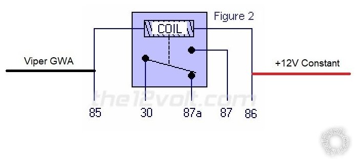
With the Viper GWA connected to Pin 85 and +12V Constant connected to Pin 86, the relay will draw no power until the Viper is armed.   Once the Viper is armed, it outputs the GWA signal which energizes the relay.
Remember that we are not including anything connected in any way to Pins 30, 87 and 87a. When the Viper outputs the GWA signal the relay will energize and draw current. While there is a momentary surge, current draw for a common 30/40 Amp relay is less than ~80 mA.
Soldering is fun!
kreg357 
Platinum - Posts: 7,783
Platinum spaceThis member has made a donation to the12volt.com. Click here for more info.spaceThis member has been recognized as an authority in Electrical Theory. Click here for more info.spaceThis member has been recognized as an authority in Mobile Security and Convenience. Click here for more info.spacespace
Joined: January 30, 2009
Location: Pennsylvania, United States
Posted: July 26, 2020 at 4:06 PM / IP Logged Link to Post Post Reply Quote kreg357
Below is a standard automotive style Bosch SPDT 30/40 Amp relay and a +12V Fuel Cutoff Relay ( N.O.) The N.O. means that the solenoid is Normally Open and will allow fuel flow until the solenoid is energized with +12V. The only time the Fuel Line Cutoff Solenoid will be energized is when the SPDT relay is energized. The relay has constant battery on one side of the coil. The coil will be controlled by the GWA signal from the Viper. When the GWA signal is present, the relay energizes and moves the wiper arm from Pin 87a to Pin 87. This will allow Chassis Ground from Pin 30 to Pin 87, completing the fuel cutoff solenoid circuit, energizing the solenoid and cutting off the fuel supply.
Viper 5806v Remote Start, MTS, Door Inputs, Window Modules -- posted image.
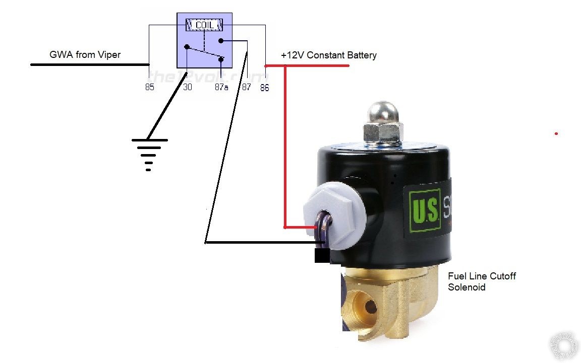
This circuit will draw no current when GWA is not present. The Viper only outputs the (-) GWA signal when it is armed. The N.O. Fuel Cutoff Solenoid will allow fuel to pass without drawing any power. Wired this way, both the relay and the Fuel Cutoff Solenoid will be drawing power while the Viper is armed and the engine is OFF. This will deplete the vehicles battery pretty quickly. Going with a more common N.C. Fuel Cutoff Solenoid will draw less power during this period but requires the solenoid to be powered to enable fuel supply to the engine. This is not a big deal with a running engine but adds another point of failure during normal operation (power loss to solenoid ).
Assuming that the vehicle needs an Ignition type circuit to allow the engine to run, switching the Red +12V Constant input power to a switched Ignition source would prevent the constant battery drain while GWA was present. Wired with IGN, the circuit would only draw current while IGN was ON and GWA was present. Below is the same circuit using IGN as power.
Viper 5806v Remote Start, MTS, Door Inputs, Window Modules -- posted image.
Soldering is fun!

If you wish to post a reply to this topic, you must first login.
If you are not already registered, you must first register.

  Printable version Printable version Post ReplyPost New Topic
You cannot post new topics in this forum
You cannot reply to topics in this forum
You cannot delete your posts in this forum
You cannot edit your posts in this forum
You cannot create polls in this forum
You cannot vote in polls in this forum

  •  
Search the12volt.com
Follow the12volt.com Follow the12volt.com on Facebook
Friday, April 19, 2024 • Copyright © 1999-2024 the12volt.com, All Rights Reserved Privacy Policy & Use of Cookies
Disclaimer: *All information on this site ( the12volt.com ) is provided "as is" without any warranty of any kind, either expressed or implied, including but not limited to fitness for a particular use. Any user assumes the entire risk as to the accuracy and use of this information. Please verify all wire colors and diagrams before applying any information.

Secured by Sectigo
the12volt.com spacer
Support the12volt.com
Top
the12volt.com spacer