the12volt.com spacer
icon

window switch illumination


Post ReplyPost New Topic
< Prev Topic Next Topic >
frans-c 
Copper - Posts: 77
Copper spacespace
Joined: February 14, 2006
Location: South Africa
Posted: June 04, 2007 at 6:30 PM / IP Logged  

Hi, guys!

I recently installed brand new OEM window regulators and motors in my car (see my signature). I also installed the Valet 712T keyless entry kit as well as two Directed 530T window modules.

The entire setup works fantastic, except for one thing: I haven't connected the window switches' illumination yet. On a previous attempt (long before I installed the OEM gear), I quickly tried to use the warning hazard flasher's illumination wire and split it to the switches' illumination connectors, but with no success. I wasn't too clued up then.

This is the factory wiring diagram that I followed for the installation:

window switch illumination -- posted image.

Obviously the two 530T modules aren't shown here, but they don't have anything to do with the illumination circuit, do they?

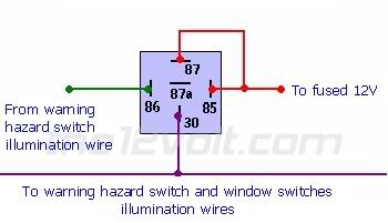
The illumination circuit (blue) starts at 62 at the top right-hand corner. What I want to do is to use a relay, using the illumination wire of the hazard warning switch as the source current, with the relay then supplying current to the hazard warning switch and the six window switches' illumination connectors. In other words, number 62 on this wiring diagram will then represent the relay that I intend on using. This is how I want to connect the relay:

window switch illumination -- posted image.

Now, I'm not too familiar yet with wiring diagrams and all the proper terminology, but as far as I can tell, there's a diode within each window switch at the illumination connector (number 6 on each switch) with the illumination current on the anode side and ground on the cathode side.

Now, my actual question is this: I took a switch and quickly connected the my positive battery terminal with the connector 6 and the negative terminal with connector 4, but nothing happened. Should the switch have illuminated or doesn't it work like this?

F R A N S
1985 Mercedes-Benz 230E
320 000 km / 199 000 miles
Full MB Service History
frans-c 
Copper - Posts: 77
Copper spacespace
Joined: February 14, 2006
Location: South Africa
Posted: June 06, 2007 at 8:47 AM / IP Logged  

So I managed to get the switches lit by reversing the polarity, i.e. connector 6 as ground and 4 as illumination source. That was the ONLY I managed to get them working.

However, when I connected the switches in the car, the window would work fine when the lights were off, but they were dead when the lights were switched on. When I changed the connectors back the way as it's shown in the diagram, the windows would work again irrespective of light status, but of course they wouldn't illuminate.

Does anybody have an idea where the problem is?

F R A N S
1985 Mercedes-Benz 230E
320 000 km / 199 000 miles
Full MB Service History

Sorry, you can NOT post a reply.
This topic is closed.

  Printable version Printable version Post ReplyPost New Topic
You cannot post new topics in this forum
You cannot reply to topics in this forum
You cannot delete your posts in this forum
You cannot edit your posts in this forum
You cannot create polls in this forum
You cannot vote in polls in this forum

  •  
Search the12volt.com
Follow the12volt.com Follow the12volt.com on Facebook
Thursday, April 25, 2024 • Copyright © 1999-2024 the12volt.com, All Rights Reserved Privacy Policy & Use of Cookies
Disclaimer: *All information on this site ( the12volt.com ) is provided "as is" without any warranty of any kind, either expressed or implied, including but not limited to fitness for a particular use. Any user assumes the entire risk as to the accuracy and use of this information. Please verify all wire colors and diagrams before applying any information.

Secured by Sectigo
the12volt.com spacer
Support the12volt.com
Top
the12volt.com spacer