the12volt.com spacer
icon

5 wire positive door locks


Post ReplyPost New Topic
< Prev Topic Next Topic >
jguidry11 
Member - Posts: 13
Member spacespace
Joined: June 25, 2007
Posted: July 04, 2007 at 8:02 PM / IP Logged  
Ok I've got a '99 Ford F-150...I have the 5 wire alternating door locks and I'm not sure where to hook my keyless entry wires. I see they have the 5 wire diagram but am I making those relays? Or are those relays already in my truck and all I need to do is hook up under the fuse box? I'm lost will someone give me the step by step on what to do...thank you.
peterubers 
Silver - Posts: 706
Silver spaceThis member has made a donation to the12volt.com. Click here for more info.spacespace
Joined: December 29, 2006
Location: United States
Posted: July 04, 2007 at 8:30 PM / IP Logged  

What brand/model of alarm are you installing?

You'll likely need to purchase separate relays to install the alarm onto the 5-wire system appropriately.  The outputs on your alarm are likely low amperage (250-500mA) (-) negative trigger lock and unlock wires.

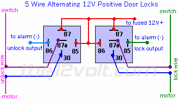
5 wire positive door locks -- posted image.

Your two wires from the alarm connect to the above inputs (alarm unlock output and alarm lock output).

You'll need to purchase two (2) SPDT 12 volts, 40amp automotive relays to pull this off.

The search function is your friend.
jguidry11 
Member - Posts: 13
Member spacespace
Joined: June 25, 2007
Posted: July 04, 2007 at 8:46 PM / IP Logged  

Where should I try these relay? In the Door panel or does it even matter?

peterubers 
Silver - Posts: 706
Silver spaceThis member has made a donation to the12volt.com. Click here for more info.spacespace
Joined: December 29, 2006
Location: United States
Posted: July 04, 2007 at 9:04 PM / IP Logged  

Do you have factory keyless entry (ie. did the Ford come with keyless entry?)  If Yes, then you have the 5wire as you suggested, and you can snag the Ford wires in the passenger kick panel:

pink / YELLOW (lock)

pink/light green (unlock)

The search function is your friend.
jguidry11 
Member - Posts: 13
Member spacespace
Joined: June 25, 2007
Posted: July 04, 2007 at 9:33 PM / IP Logged  
Ok thank you so much for the help. I will try it tomorrow and check back in with you guys.
peterubers 
Silver - Posts: 706
Silver spaceThis member has made a donation to the12volt.com. Click here for more info.spacespace
Joined: December 29, 2006
Location: United States
Posted: July 04, 2007 at 9:39 PM / IP Logged  
Test ALL wires with a voltmeter before you tie in any alarm wires to ford wires -- use the master lock/unlock switch at the driver's door to test voltages in wires.
The search function is your friend.
jguidry11 
Member - Posts: 13
Member spacespace
Joined: June 25, 2007
Posted: July 05, 2007 at 2:20 PM / IP Logged  
When it says to tie in to the motor...they are talking about the door lock actuator wires right?      Pk/Bk=Lock     Pk/Org=Unlock
peterubers 
Silver - Posts: 706
Silver spaceThis member has made a donation to the12volt.com. Click here for more info.spacespace
Joined: December 29, 2006
Location: United States
Posted: July 05, 2007 at 3:37 PM / IP Logged  
that's correct.  Your wire colors are correct.  You'll split each wire and tie in the respective wires from your relays to each new end
The search function is your friend.
jguidry11 
Member - Posts: 13
Member spacespace
Joined: June 25, 2007
Posted: July 07, 2007 at 12:58 PM / IP Logged  

Am I actually cutting the switch and motor wires in half? Or am I just hooking up to them? Cuz I'm not seeing how it would work if I were to cut them...

peterubers 
Silver - Posts: 706
Silver spaceThis member has made a donation to the12volt.com. Click here for more info.spacespace
Joined: December 29, 2006
Location: United States
Posted: July 07, 2007 at 1:55 PM / IP Logged  
you cut them in half -- it works becuase the relays have a normally open and a normally closed circuit (two circuits total).  The normally closed circuit will conduct the signal as if you never cut the wire in half -- the normally open circuit will close to accomodate alarm sigals to be sent to the lock/unlock motor wires.
The search function is your friend.
Page of 2

  Printable version Printable version Post ReplyPost New Topic
You cannot post new topics in this forum
You cannot reply to topics in this forum
You cannot delete your posts in this forum
You cannot edit your posts in this forum
You cannot create polls in this forum
You cannot vote in polls in this forum

  •  
Search the12volt.com
Follow the12volt.com Follow the12volt.com on Facebook
Thursday, April 18, 2024 • Copyright © 1999-2024 the12volt.com, All Rights Reserved Privacy Policy & Use of Cookies
Disclaimer: *All information on this site ( the12volt.com ) is provided "as is" without any warranty of any kind, either expressed or implied, including but not limited to fitness for a particular use. Any user assumes the entire risk as to the accuracy and use of this information. Please verify all wire colors and diagrams before applying any information.

Secured by Sectigo
the12volt.com spacer
Support the12volt.com
Top
the12volt.com spacer