


Posted: January 09, 2010 at 6:10 PM / IP Logged
 Both the Keypad and the doorfone work off of a 12v DC transformer. In the above diagram A only the keypad will unlock the lock. When I try to unlock with the Doorfone, you can hear it click and working, but nothing happens. For the Doorfone, power is being run to the negative(-) end of the doorstrike contact. The doorfone works when i connect it directly to the lock without the keypad. I assume the doorfone has an open collector transistor to short the - side to the negative supply of the keylock when connected directly. The doorfone only seems to work if both the + and - door strike contacts are connected to the lock.
My question is can I make both doorfone and keypad work with this configuration? Do I need to add a separate DPDT relay? If so, what would the wiring look like. Thanks for any help on this!
Both the Keypad and the doorfone work off of a 12v DC transformer. In the above diagram A only the keypad will unlock the lock. When I try to unlock with the Doorfone, you can hear it click and working, but nothing happens. For the Doorfone, power is being run to the negative(-) end of the doorstrike contact. The doorfone works when i connect it directly to the lock without the keypad. I assume the doorfone has an open collector transistor to short the - side to the negative supply of the keylock when connected directly. The doorfone only seems to work if both the + and - door strike contacts are connected to the lock.
My question is can I make both doorfone and keypad work with this configuration? Do I need to add a separate DPDT relay? If so, what would the wiring look like. Thanks for any help on this!


Posted: January 09, 2010 at 8:12 PM / IP Logged
Posted: January 09, 2010 at 9:23 PM / IP Logged
Posted: January 09, 2010 at 9:36 PM / IP Logged
Posted: January 09, 2010 at 11:23 PM / IP Logged

Posted: January 10, 2010 at 6:19 AM / IP Logged

Posted: January 10, 2010 at 1:46 PM / IP Logged
Posted: January 10, 2010 at 1:55 PM / IP Logged
Posted: January 10, 2010 at 3:56 PM / IP Logged

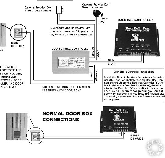 The extra door strike controller shown is probably a relay, so your Door Fone output (which is NOT a dry contact but a low output control for a relay) is not able to drive the door solenoid directly.
If you check that the red output from the door fone is 12V, you can simply add a relay and the COM and NO terminals (30 and 87) will provide the "dry" contacts you need for your connection.
The extra door strike controller shown is probably a relay, so your Door Fone output (which is NOT a dry contact but a low output control for a relay) is not able to drive the door solenoid directly.
If you check that the red output from the door fone is 12V, you can simply add a relay and the COM and NO terminals (30 and 87) will provide the "dry" contacts you need for your connection.Posted: January 10, 2010 at 4:12 PM / IP Logged
 Printable version
| You cannot post new topics in this forum You cannot reply to topics in this forum You cannot delete your posts in this forum You cannot edit your posts in this forum You cannot create polls in this forum You cannot vote in polls in this forum |

| Search the12volt.com |
Follow the12volt.com 
Thursday, April 25, 2024 • Copyright © 1999-2024 the12volt.com, All Rights Reserved • Privacy Policy & Use of Cookies

Thursday, April 25, 2024 • Copyright © 1999-2024 the12volt.com, All Rights Reserved • Privacy Policy & Use of Cookies
Disclaimer:
*All information on this site ( the12volt.com ) is provided "as is" without any warranty of any kind, either expressed or implied, including but not limited to fitness for a particular use. Any user assumes the entire risk as to the accuracy and use of this information. Please
verify all wire colors and diagrams before applying any information.
