the12volt.com spacer
icon

identifying relay pins


Post ReplyPost New Topic
< Prev Topic Next Topic >
juavos00 
Copper - Posts: 66
Copper spacespace
Joined: August 05, 2003
Location: Texas, United States
Posted: April 17, 2010 at 5:18 PM / IP Logged  

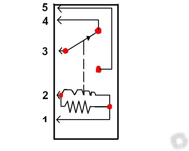
First off sorry for the crappy paint drawing, but thats as good as I could do. Anyway I need help identifying the pins on this relay. (85,86,87,87a,30) Thanks

identifying relay pins -- posted image.

t&t tech 
Platinum - Posts: 2,608
Platinum spacespace
Joined: October 05, 2008
Location: Trinidad and Tobago
Posted: April 17, 2010 at 5:27 PM / IP Logged  

85- Negative side of relay coil*

86- Positive side of relay coil*

30- Common terminal of relay,

87a- Normally closed terminal (closed to pin 30 when relay is inactive, and open when active)

87- Normally open pin, (open when inactive, closed to pin 30 when relay is active)

*Applying power and ground to the respective termnal activates the relay!

commit your way to jehovah and he will act in your behalf. psalms 37:5
t&t tech 
Platinum - Posts: 2,608
Platinum spacespace
Joined: October 05, 2008
Location: Trinidad and Tobago
Posted: April 17, 2010 at 5:29 PM / IP Logged  

In the diagram you have however

Pins 1 and 2 would be the coil

pin 3 is common, 4 is normally closed and 5 normally open!

commit your way to jehovah and he will act in your behalf. psalms 37:5
juavos00 
Copper - Posts: 66
Copper spacespace
Joined: August 05, 2003
Location: Texas, United States
Posted: April 17, 2010 at 5:30 PM / IP Logged  

thanks for the reply, but that doesn't help me much. I know about what each pin does, but that is why I drew the picture with the numbers on them hoping someone would say.. 1 = 85 2 = 86, so forth and so on.

Also does it matter if the positive and negative are switched?

juavos00 
Copper - Posts: 66
Copper spacespace
Joined: August 05, 2003
Location: Texas, United States
Posted: April 17, 2010 at 5:31 PM / IP Logged  

sorry couldnt post before you answered my question..

But does the positive and negative matter?

oldspark 
Gold - Posts: 4,913
Gold spacespace
Joined: November 03, 2008
Location: Australia
Posted: April 17, 2010 at 7:30 PM / IP Logged  
Not in this case - you relay uses a resistor across the coil (not a diode to quench the coil spark).
i am an idiot 
Platinum - Posts: 13,667
Platinum spaceThis member consistently provides reliable informationspace
Joined: September 21, 2006
Location: Louisiana, United States
Posted: April 17, 2010 at 9:09 PM / IP Logged  

1 = 85

2 = 86

3 = 30

4 =87A

5 = 87

howie ll 
Pot Metal - Posts: 16,466
Pot Metal spacespace
Joined: January 09, 2007
Location: United Kingdom
Posted: April 18, 2010 at 12:21 PM / IP Logged  
I think that relay is Italian, the convention is pin 1 (85 on the ISO listing) is normally the neg. side of the coil.
t&t tech 
Platinum - Posts: 2,608
Platinum spacespace
Joined: October 05, 2008
Location: Trinidad and Tobago
Posted: April 18, 2010 at 3:25 PM / IP Logged  
My bad!  You should have explained yourself better!
commit your way to jehovah and he will act in your behalf. psalms 37:5
juavos00 
Copper - Posts: 66
Copper spacespace
Joined: August 05, 2003
Location: Texas, United States
Posted: April 18, 2010 at 8:03 PM / IP Logged  
I have wired in my relay thanks to all of your help.. Mods can you please lock and/or delete this thread. Thanks

Sorry, you can NOT post a reply.
This topic is closed.

  Printable version Printable version Post ReplyPost New Topic
You cannot post new topics in this forum
You cannot reply to topics in this forum
You cannot delete your posts in this forum
You cannot edit your posts in this forum
You cannot create polls in this forum
You cannot vote in polls in this forum

  •  
Search the12volt.com
Follow the12volt.com Follow the12volt.com on Facebook
Friday, April 19, 2024 • Copyright © 1999-2024 the12volt.com, All Rights Reserved Privacy Policy & Use of Cookies
Disclaimer: *All information on this site ( the12volt.com ) is provided "as is" without any warranty of any kind, either expressed or implied, including but not limited to fitness for a particular use. Any user assumes the entire risk as to the accuracy and use of this information. Please verify all wire colors and diagrams before applying any information.

Secured by Sectigo
the12volt.com spacer
Support the12volt.com
Top
the12volt.com spacer