the12volt.com spacer
icon

flip flop circuit with constant switch


Post ReplyPost New Topic
< Prev Topic Next Topic >
shifto 
Member - Posts: 2
Member spacespace
Joined: May 12, 2015
Location: Oregon, United States
Posted: May 12, 2015 at 1:02 AM / IP Logged Link to Post Post Reply Quote shifto
I'm trying to figure out how to switch between two inputs with a single constant switch rather than a momentary. All of the flip flop relay circuits I have found use a momentary switch.
I'd like to use the power switch on a radio for this. Turn on and input 1 is selected, turn off, then turn on again and input 2 is selected.
The only thing I can think of is to use a circuit to "convert" the constant switch to give a momentary output and use that to trigger the flip flop circuit.
Any thoughts would be appreciated!
davep. 
Gold - Posts: 641
Gold spacespace
Joined: May 27, 2011
Location: California, United States
Posted: May 12, 2015 at 3:18 PM / IP Logged Link to Post Post Reply Quote davep.
shifto wrote:
I'm trying to figure out how to switch between two inputs with a single constant switch rather than a momentary. All of the flip flop relay circuits I have found use a momentary switch.
I've thought about this question for a day. The answer is "the control doesn't matter if the switch is constant or momentary". The constant-on switch is like holding the button down indefinitely. It won't hurt anything, and turning the switch off is the same as finally lifting your finger off the button.
Look at this diagram. You will have to change terminal 85 on the far right, and far left relays to GND, so it will respond to a (+) trigger at the switch/button.
flip flop circuit with constant switch -- posted image.
When the power comes on, it will turn the latch on.
When the power goes off, the trigger relays (far left, and 3rd from left relay) will change state.
Power on again, latch turns off.
Power off, trigger (right 2 relays, purple) changes state.
Rinse and repeat.
Connect the output of the array (blue) to as many double-throw relay coils as you need to do the switching you require. The N.O. contacts in these relays will be the array ON, and the N.C contacts will be the array OFF.
I offer one caution. You must connect the "Constant 12V supply (red) to an IGN or ACCY source because if the array is ON when you shut the IGN off, the array will stay energized until the battery goes dead. With 3 coils energized, the draw is significant. When you do this, the initial power-up of the radio will always result in the array turning ON. so make the N.O. contacts of your switcher relays the priority.
This should get you going.
hotwaterwizard 
Silver - Posts: 1,350
Silver spacespace
Joined: December 11, 2003
Location: California, United States
Posted: May 12, 2015 at 10:03 PM / IP Logged Link to Post Post Reply Quote hotwaterwizard
NICE ONE LET ME THINK ABOUT IT
John DeRosa (Hotwaterwizard)
Stockton California
When in doubt, try it out !
shifto 
Member - Posts: 2
Member spacespace
Joined: May 12, 2015
Location: Oregon, United States
Posted: May 12, 2015 at 10:12 PM / IP Logged Link to Post Post Reply Quote shifto
Interesting thought that the control does not matter. I guess I was hoping for a solution that would not leave the relays energized the whole time.
It does have me thinking about using latching relays to simplify things.
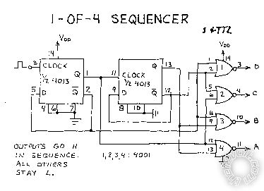
I'm also thinking about some sort of sequential circuit that could switch between 3 inputs.
To take a step back, I'm wondering how the power switch on the radio could be used to switch inputs each time it is powered on and off.
Thanks for your input!
hotwaterwizard 
Silver - Posts: 1,350
Silver spacespace
Joined: December 11, 2003
Location: California, United States
Posted: May 12, 2015 at 10:26 PM / IP Logged Link to Post Post Reply Quote hotwaterwizard
flip flop circuit with constant switch -- posted image.
John DeRosa (Hotwaterwizard)
Stockton California
When in doubt, try it out !
hotwaterwizard 
Silver - Posts: 1,350
Silver spacespace
Joined: December 11, 2003
Location: California, United States
Posted: May 12, 2015 at 10:28 PM / IP Logged Link to Post Post Reply Quote hotwaterwizard
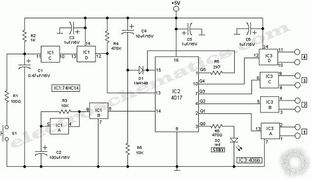
Every time power is switched on and off the circuit switches to a different input. just add a switch to turn the circuit on and off.
John DeRosa (Hotwaterwizard)
Stockton California
When in doubt, try it out !
hotwaterwizard 
Silver - Posts: 1,350
Silver spacespace
Joined: December 11, 2003
Location: California, United States
Posted: May 12, 2015 at 10:41 PM / IP Logged Link to Post Post Reply Quote hotwaterwizard
flip flop circuit with constant switch -- posted image.
John DeRosa (Hotwaterwizard)
Stockton California
When in doubt, try it out !
howie ll 
Pot Metal - Posts: 16,466
Pot Metal spacespace
Joined: January 09, 2007
Location: United Kingdom
Posted: May 13, 2015 at 6:26 AM / IP Logged Link to Post Post Reply Quote howie ll
Is this relevant? Back in the day Rolls Royce OEM and myself for aftermarket installs did the following.
You had a radio and an 8 track or cassette.
Both are powered and when the radio is switched on the remote antenna feed (or tap it's on/off) then switched an 8 pole changeover relay for the speakers.
I also did that for a home combi 20 years ago, Sony Profeel with it's own speakers, turned on the Yamaha amp and the outputs switched to "proper" speakers.
hotwaterwizard 
Silver - Posts: 1,350
Silver spacespace
Joined: December 11, 2003
Location: California, United States
Posted: May 13, 2015 at 7:59 PM / IP Logged Link to Post Post Reply Quote hotwaterwizard
YES YES YES I remember those.They use to sell a box at Radio Shack for the CB that used the Car Speakers when the CB was on.
John DeRosa (Hotwaterwizard)
Stockton California
When in doubt, try it out !
howie ll 
Pot Metal - Posts: 16,466
Pot Metal spacespace
Joined: January 09, 2007
Location: United Kingdom
Posted: May 13, 2015 at 11:39 PM / IP Logged Link to Post Post Reply Quote howie ll
Are you as old as me then?
In those days it was 4 pole relays plus the double gang front back fader pot!
RR used to mount them on a lovely PCB under the radio with a common ground on the (-) speaker side.
Page of 2

  Printable version Printable version Post ReplyPost New Topic
You cannot post new topics in this forum
You cannot reply to topics in this forum
You cannot delete your posts in this forum
You cannot edit your posts in this forum
You cannot create polls in this forum
You cannot vote in polls in this forum

  •  
Search the12volt.com
Follow the12volt.com Follow the12volt.com on Facebook
Thursday, April 18, 2024 • Copyright © 1999-2024 the12volt.com, All Rights Reserved Privacy Policy & Use of Cookies
Disclaimer: *All information on this site ( the12volt.com ) is provided "as is" without any warranty of any kind, either expressed or implied, including but not limited to fitness for a particular use. Any user assumes the entire risk as to the accuracy and use of this information. Please verify all wire colors and diagrams before applying any information.

Secured by Sectigo
the12volt.com spacer
Support the12volt.com
Top
the12volt.com spacer