


multiple horns with one switch


Posted: August 16, 2006 at 7:24 AM / IP Logged
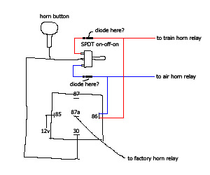 I want to have 3 different types of horns and honk either one of the three in certain situations. But no more than one horn will be honked at the same time. All 3 of them use negative pulse to energize their respective relay.
I will use the factory horn most of the time and center-off the SPDT switch so when the factory horn honks the air/train horns are disabled, if my logic is correct, even though the middle pin of the SPDT switch has ground ready when the horn button is pushed, but if it sits at center-off position, so both train/air horns do nothing.
However, if either the train horn or air horn honks, if I am correct, it should energize the normally-closed relay on my diagram and connect pin 30 to pin 87, as if the factory horn wire was cut off.
Let me know if this still makes sense.
My major question would be, do I need the diode on blue and red wire? If so, are they in the right position and direction to protect my switch? Do I need a fuse the 12v+ at pin85 on the relay, 5A? Basically everywhere except pin85 on the diagram is using ground signal.
Do you see any problem with this multi-horn setup? Or any better solution?
I want to have 3 different types of horns and honk either one of the three in certain situations. But no more than one horn will be honked at the same time. All 3 of them use negative pulse to energize their respective relay.
I will use the factory horn most of the time and center-off the SPDT switch so when the factory horn honks the air/train horns are disabled, if my logic is correct, even though the middle pin of the SPDT switch has ground ready when the horn button is pushed, but if it sits at center-off position, so both train/air horns do nothing.
However, if either the train horn or air horn honks, if I am correct, it should energize the normally-closed relay on my diagram and connect pin 30 to pin 87, as if the factory horn wire was cut off.
Let me know if this still makes sense.
My major question would be, do I need the diode on blue and red wire? If so, are they in the right position and direction to protect my switch? Do I need a fuse the 12v+ at pin85 on the relay, 5A? Basically everywhere except pin85 on the diagram is using ground signal.
Do you see any problem with this multi-horn setup? Or any better solution?
Posted: August 18, 2006 at 11:51 AM / IP Logged
Posted: August 20, 2006 at 4:10 AM / IP Logged

Posted: August 20, 2006 at 11:56 AM / IP Logged

Posted: September 26, 2006 at 8:14 PM / IP Logged
Posted: September 27, 2006 at 5:16 AM / IP Logged
Posted: September 27, 2006 at 8:23 AM / IP Logged
Posted: September 27, 2006 at 10:19 AM / IP Logged
Sorry, you can NOT post a reply.
This topic is closed.
 Printable version
| You cannot post new topics in this forum You cannot reply to topics in this forum You cannot delete your posts in this forum You cannot edit your posts in this forum You cannot create polls in this forum You cannot vote in polls in this forum |

| Search the12volt.com |
Follow the12volt.com 
Tuesday, April 23, 2024 • Copyright © 1999-2024 the12volt.com, All Rights Reserved • Privacy Policy & Use of Cookies

Tuesday, April 23, 2024 • Copyright © 1999-2024 the12volt.com, All Rights Reserved • Privacy Policy & Use of Cookies
Disclaimer:
*All information on this site ( the12volt.com ) is provided "as is" without any warranty of any kind, either expressed or implied, including but not limited to fitness for a particular use. Any user assumes the entire risk as to the accuracy and use of this information. Please
verify all wire colors and diagrams before applying any information.
