the12volt.com spacer
icon

reverse polarity with a twist.


Post ReplyPost New Topic
< Prev Topic Next Topic >
hyperryd 
Member - Posts: 28
Member spacespace
Joined: November 12, 2006
Location: United States
Posted: March 08, 2007 at 11:58 PM / IP Logged  

OK, I have searched around and I can't find what I am looking for so here is my question.

I have a switch that puts a negative feed out on a wire on the down position and then a positive feed out in the up position on the same wire.  I want two different positive feeds to power two different electric valves.  There is no way to rewire the switch as it is a sealed switch that I don’t want to mess with the internals.

Wiring a relay to convert the negative over to positive is no problem.  The problem is I have split the wire with one side going directly to the valve and the other wire going to the negative side of the reversing relay.  The wire going to the relay is getting negative feedback from the other leg going to the valve, which charges the relay all the time.  If I use a diode on the valve leg, to stop the negative feedback, positive flow is stopped from going to the valve.  If I use a diode on the relay leg, negative flow is stopped so the negative signal from the switch is lost.

I have tried so many relay and diode configurations and all I have is a headache.  I know this is possible, but I have hit a mental wall.  I know I am staring right at the solution, but I can't see the forest through all of the trees.  I'm not sure if a resistor would help here and I am resistor illiterate. Any help would be appreciated

frydchkn 
Copper - Posts: 60
Copper spacespace
Joined: March 11, 2006
Location: United States
Posted: March 09, 2007 at 12:35 AM / IP Logged  

How about permanently grounding one valve, with a positive trigger from the switch. And have the other valve with constant power, but with a negative trigger from the switch.  -no need for relays.

What are the valves controlling? just curious

hyperryd 
Member - Posts: 28
Member spacespace
Joined: November 12, 2006
Location: United States
Posted: March 09, 2007 at 6:42 AM / IP Logged  

You know I was laying in bed last night thinking the same thing, but thinking that I might still get feedback that would be enough to trigger the other valve, but I will try it later today when I get off of work just to see.

These are airbag valves to lay out a 1965 Cadillac using a 1965 6-way power seat switch.  My friend doesn't want any modern switches in the interior.

hyperryd 
Member - Posts: 28
Member spacespace
Joined: November 12, 2006
Location: United States
Posted: March 09, 2007 at 6:47 PM / IP Logged  
No, such luck.  The coils on the valves feed back once one valve is activated and both valves stay open.  This is really frustrating.
hotwaterwizard 
Silver - Posts: 1,350
Silver spacespace
Joined: December 11, 2003
Location: California, United States
Posted: March 09, 2007 at 10:42 PM / IP Logged  
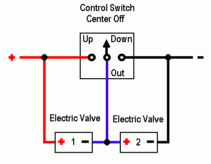
reverse polarity with a twist. -- posted image.
John DeRosa (Hotwaterwizard)
Stockton California
When in doubt, try it out !
hyperryd 
Member - Posts: 28
Member spacespace
Joined: November 12, 2006
Location: United States
Posted: March 09, 2007 at 10:53 PM / IP Logged  

The problem is if I activate valve number two the negative crosses the coil and energizes valve number one, and visa versa.

Great diagram for my switch though.  Thanks.

hotwaterwizard 
Silver - Posts: 1,350
Silver spacespace
Joined: December 11, 2003
Location: California, United States
Posted: March 09, 2007 at 11:59 PM / IP Logged  

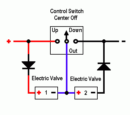
Just add a couple of General Purpose Diodes.

reverse polarity with a twist. -- posted image.

John DeRosa (Hotwaterwizard)
Stockton California
When in doubt, try it out !
dualsport 
Silver - Posts: 983
Silver spacespace
Joined: September 27, 2005
Location: United States
Posted: March 09, 2007 at 11:59 PM / IP Logged  
Here's a possible circuit you can try-
reverse polarity with a twist. -- posted image.
It uses two zener diodes to block the current path from 12V to ground, (assuming your switching signal is open circuit when off, and either 12V or ground when you hit the switch.
The transistors amplify the current signal to switch the relays and give you the two (+) outputs. If you don't need much current you could do without the K1 relay and just use the output of the transistor. You might need to diddle with the resistance values and select the appropriate transistor part depending on the relay or signal input that you're planning on driving with it.
hotwaterwizard 
Silver - Posts: 1,350
Silver spacespace
Joined: December 11, 2003
Location: California, United States
Posted: March 10, 2007 at 12:03 AM / IP Logged  
Keep it simple. Try the Diodes. Trust me it will work.
John DeRosa (Hotwaterwizard)
Stockton California
When in doubt, try it out !
dualsport 
Silver - Posts: 983
Silver spacespace
Joined: September 27, 2005
Location: United States
Posted: March 10, 2007 at 12:09 AM / IP Logged  
The problem is the diodes are not back to back in the series chain, so current will be constantly flowing through them, and the valves.
If this is for a car application, it'll be a drain on the battery, assuming the valves won't remain switched on with 1/2 battery voltage.
The drop out voltage of the valves might be low enough that the valves will remain on once they're energized.
How much current do the valves need to operate? If it's fairly high, you really need to use relays; or some hefty diodes, since they'd need to pass all the current needed by the valves.
Page of 5

  Printable version Printable version Post ReplyPost New Topic
You cannot post new topics in this forum
You cannot reply to topics in this forum
You cannot delete your posts in this forum
You cannot edit your posts in this forum
You cannot create polls in this forum
You cannot vote in polls in this forum

  •  
Search the12volt.com
Follow the12volt.com Follow the12volt.com on Facebook
Friday, April 19, 2024 • Copyright © 1999-2024 the12volt.com, All Rights Reserved Privacy Policy & Use of Cookies
Disclaimer: *All information on this site ( the12volt.com ) is provided "as is" without any warranty of any kind, either expressed or implied, including but not limited to fitness for a particular use. Any user assumes the entire risk as to the accuracy and use of this information. Please verify all wire colors and diagrams before applying any information.

Secured by Sectigo
the12volt.com spacer
Support the12volt.com
Top
the12volt.com spacer