the12volt.com spacer
icon

will this burn up actuator?


Post ReplyPost New Topic
< Prev Topic Next Topic >
mrcanngo 
Copper - Posts: 63
Copper spacespace
Joined: March 17, 2007
Posted: April 07, 2007 at 10:31 PM / IP Logged  

I was going to hookup to relays to an actuator.  Question, if i have my actuator being fed a constant 12volts will it end up burning the actuator? Like if i make it so that its always got a  positve 12volts on one side and ground out the other side would i ruin something or drain the battery?

Thanks, i know its a dumb question but it would save me a lot trouble and time.

mando2155 
Copper - Posts: 74
Copper spacespace
Joined: April 03, 2006
Location: United States
Posted: April 07, 2007 at 11:19 PM / IP Logged  
yes if you had constant ground on one side of the actuator and constant 12v on the other side you will kill the actuator and drain your battery.  Actuators are meant to be used momentarily.  What is it your trying to do with the actuator?
mrcanngo 
Copper - Posts: 63
Copper spacespace
Joined: March 17, 2007
Posted: April 07, 2007 at 11:32 PM / IP Logged  

I'm trying to make my actuator open and close all in one pulse.

So basically when i hit the trunk pop on my alarm, my actuator to the trunk will unlock and lock.

Your probably wondering why i'd want that. It is complicated to explain but i'll try.  Basically the "unlock" portion of the trunk would make it pop up.  Without the "lock" portion, the trunk will go down but the mechanical latch won't shut. Reason is that while the actuator is in the "unlock" position, the motor inside is in the "closed" state.  Because of this "closed" state, the trunk's mechanical latch is to weak to pull the actuator back the the original position. 

I know that if i can make the trunk actuator go open and closed, this will solve all my problems.

Thanks for the help!

hotwaterwizard 
Silver - Posts: 1,350
Silver spacespace
Joined: December 11, 2003
Location: California, United States
Posted: April 08, 2007 at 1:07 AM / IP Logged  

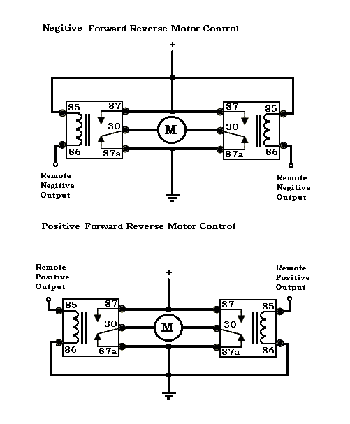
nice challange. Lets start with the basic circuit. Pick which one best fits your alarm.

will this burn up actuator? -- posted image.

https://www.the12volt.com/installbay/forum_posts.asp?tid=90977&PN=1

John DeRosa (Hotwaterwizard)
Stockton California
When in doubt, try it out !
mrcanngo 
Copper - Posts: 63
Copper spacespace
Joined: March 17, 2007
Posted: April 08, 2007 at 1:32 AM / IP Logged  

thanks for the nifty diagram wizard!

Maybe i''m not understanding right but is this assuming i have 2 negative outputs available?

Sorry for my ignorance. I wanted to baiscally have the polarities swap sides all in one button push using just one negative output from alarm (since thats all i have).  From what i understand, please correct me if i'm wrong: The diagram you proposed makes it so that if i push the button once, it will unlock, push again and it will lock right?

hotwaterwizard 
Silver - Posts: 1,350
Silver spacespace
Joined: December 11, 2003
Location: California, United States
Posted: April 08, 2007 at 1:50 AM / IP Logged  

This diagram has a seperate lock and unlock signal. Here is why I picked this one.

You only need one function by what you say. unlock function. Now we figure out how to hook the constant to momentary circuit to the other side for automatic locking action.

I need to know if we have a Negitive pulse or a positive Pulse.

John DeRosa (Hotwaterwizard)
Stockton California
When in doubt, try it out !
mrcanngo 
Copper - Posts: 63
Copper spacespace
Joined: March 17, 2007
Posted: April 08, 2007 at 1:52 AM / IP Logged  

i have a negative pulse from my alarm.

Thanks Wizard!

hotwaterwizard 
Silver - Posts: 1,350
Silver spacespace
Joined: December 11, 2003
Location: California, United States
Posted: April 08, 2007 at 1:58 AM / IP Logged  
Ok I will work on it tomorrow.
John DeRosa (Hotwaterwizard)
Stockton California
When in doubt, try it out !
hotwaterwizard 
Silver - Posts: 1,350
Silver spacespace
Joined: December 11, 2003
Location: California, United States
Posted: April 08, 2007 at 2:23 AM / IP Logged  

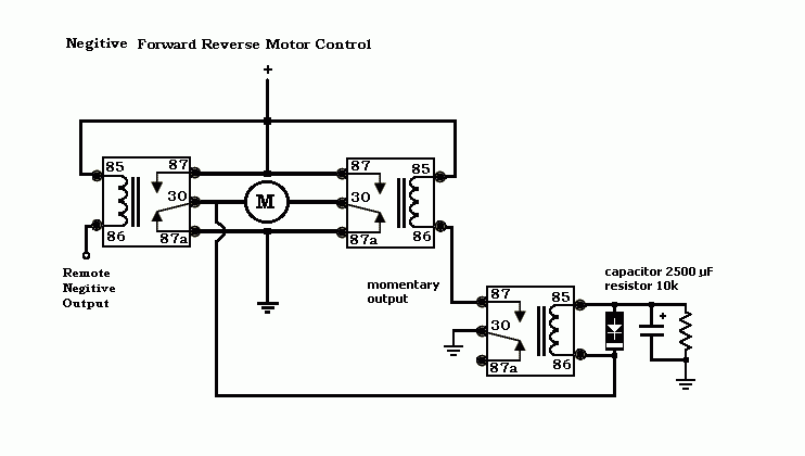
Here is what I came up with so far.

The Diode is a standard diode like 1N2001 1N2002 1N2004

it stops the coil from dammaging the capacitor and resistor.

will this burn up actuator? -- posted image.

John DeRosa (Hotwaterwizard)
Stockton California
When in doubt, try it out !
mrcanngo 
Copper - Posts: 63
Copper spacespace
Joined: March 17, 2007
Posted: April 08, 2007 at 2:28 AM / IP Logged  
i have no idea if that will work but i trust your opinion because of all your other posts that i have read.  Btw, i know the squiggly thing is a resistor and the one to the left of it is a capacitor, but what is the one to the left of that? a diode of sorts? if so, what rating diode should i get?
Page of 3

  Printable version Printable version Post ReplyPost New Topic
You cannot post new topics in this forum
You cannot reply to topics in this forum
You cannot delete your posts in this forum
You cannot edit your posts in this forum
You cannot create polls in this forum
You cannot vote in polls in this forum

  •  
Search the12volt.com
Follow the12volt.com Follow the12volt.com on Facebook
Tuesday, April 23, 2024 • Copyright © 1999-2024 the12volt.com, All Rights Reserved Privacy Policy & Use of Cookies
Disclaimer: *All information on this site ( the12volt.com ) is provided "as is" without any warranty of any kind, either expressed or implied, including but not limited to fitness for a particular use. Any user assumes the entire risk as to the accuracy and use of this information. Please verify all wire colors and diagrams before applying any information.

Secured by Sectigo
the12volt.com spacer
Support the12volt.com
Top
the12volt.com spacer