


2009 infiniti fx35
Home /
the12volt's Install Bay /
Vehicle Wiring Information & File Requests / 2009 infiniti fx35 ( Topic Closed)


Posted: April 18, 2012 at 3:15 AM / IP Logged


Posted: April 18, 2012 at 6:57 AM / IP Logged
Posted: April 18, 2012 at 10:25 AM / IP Logged
Posted: April 19, 2012 at 10:21 PM / IP Logged
Posted: April 19, 2012 at 11:09 PM / IP Logged

Posted: April 20, 2012 at 3:40 AM / IP Logged
Posted: April 21, 2012 at 12:24 PM / IP Logged
Posted: April 21, 2012 at 1:55 PM / IP Logged
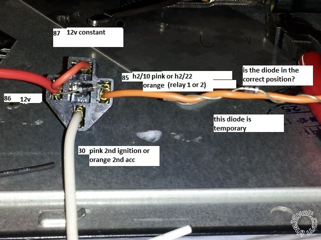
 The right hand temp diode is correct just cut the orange and pink and mount the diode in line. Your band position on both is correct.
Posted: April 21, 2012 at 2:40 PM / IP Logged
Posted: April 21, 2012 at 9:14 PM / IP Logged
 Printable version
| You cannot post new topics in this forum You cannot reply to topics in this forum You cannot delete your posts in this forum You cannot edit your posts in this forum You cannot create polls in this forum You cannot vote in polls in this forum |

| Search the12volt.com |
Follow the12volt.com 
Friday, April 19, 2024 • Copyright © 1999-2024 the12volt.com, All Rights Reserved • Privacy Policy & Use of Cookies

Friday, April 19, 2024 • Copyright © 1999-2024 the12volt.com, All Rights Reserved • Privacy Policy & Use of Cookies
Disclaimer:
*All information on this site ( the12volt.com ) is provided "as is" without any warranty of any kind, either expressed or implied, including but not limited to fitness for a particular use. Any user assumes the entire risk as to the accuracy and use of this information. Please
verify all wire colors and diagrams before applying any information.
