Item Wire Color Polarity Wire Location
12 Volts green/red (50A) + BCM in passenger kick, 22 pin plug (G), pin 22
Ground (chassis ground)
Starter blue/white + ignition switch, black 7 pin plug, pin 7
Ignition white/orange + ignition switch, black 7 pin plug, pin 1
Accessory violet/green + ignition switch, black 7 pin plug, pin 6
Keysense blue/gray + ignition switch, black 7 pin plug, pin 5
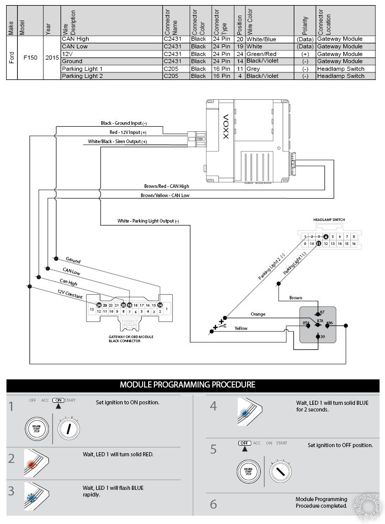
CAN Bus High white/blue (HS CAN) data Gateway Module on data link connector, black 24 pin plug, pin 20
CAN Bus Low white (HS CAN) data Gateway Module on data link connector, black 24 pin plug, pin 19
CAN Bus High 2 gray/orange (MS CAN) data Gateway Module on data link connector, black 24 pin plug, pin 23
CAN Bus Low 2 violet/orange (MS CAN) data Gateway Module on data link connector, black 24 pin plug, pin 22
CAN Bus High 3 green/orange (HS2 CAN) data Gateway Module on data link connector, black 24 pin plug, pin 18
CAN Bus Low 3 gray/blue (HS2 CAN) data Gateway Module on data link connector, black 24 pin plug, pin 17
IMMO Data blue/white (LIN bus) data PATS Transceiver on ignition switch, black 4 pin plug, pin 3
Power Lock gray/yellow - door lock switch in driver door, black 4 pin plug, pin 1 or black 8 pin plug, pin 7
Power Unlock violet/gray - door lock switch in driver door, black 4 pin plug, pin 3 or black 8 pin plug, pin 8
Lock Motor gray/brown 5 wire driver kick or BCM in passenger kick, 36 pin plug (C), pin 35
Driver Unlock Motor blue/green 5 wire driver kick or BCM in passenger kick, 36 pin plug (C), pin 27
Passenger Unlock Motor brown/green 5 wire BCM in passenger kick, 36 pin plug (C), pin 32
Factory Alarm Arm (arms on lock)
Factory Alarm Disarm (see disarm no unlock)
Disarm No Unlock (transponder and ignition)
Parking Lights blue/gray (F); blue/gray (R) + BCM in passenger kick, 22 pin plug (G), pin 3; 36 pin plug (C), pin 12
Parking Lights - gray - headlight switch, black 16 pin plug, pin 11
Note - Parking Lights -: See Tech Doc 1096
Parking Lights Interrupt black/violet cut headlight switch, black 16 pin plug, pin 4
Note - Parking Lights Interrupt: See Tech Doc 1096
Hazards brown - hazard switch or BCM in passenger kick, black 52 pin plug (B), pin 19
Turn Signal (Left) blue/green (F); gray/orange (R) + BCM in passenger kick, 40 pin plug (F), pin 39; 52 pin plug (E), pin 26
Turn Signal (Right) yellow/violet (F); green/orange (R) + BCM in passenger kick, 40 pin plug (F), pin 38; 52 pin plug (E), pin 52
Headlight blue - headlight switch, black 16 pin plug, pin 12
AutoLights violet cut headlight switch, black 16 pin plug, pin 13
Reverse Light green/brown + driver kick or BCM in passenger kick, 36 pin plug (C), pin 11
Left Front Door Trigger brown - N.C. driver kick, harness to rear or BCM in passenger kick, 52 pin plug (E), pin 33
Right Front Door Trigger white - N.C. BCM in passenger kick, 52 pin plug (E), pin 21
Left Rear Door Trigger green - N.C. BCM in passenger kick, 52 pin plug (E), pin 46
Right Rear Door Trigger yellow - N.C. BCM in passenger kick, 52 pin plug (E), pin 19
Dome Light gray/violet + BCM in passenger kick, 36 pin plug (C), pin 13
Trunk/Hatch Pin brown/yellow or yellow/orange (tailgate ajar) - driver kick or BCM in passenger kick, 52 pin plug (E), pin 34
Hood Pin blue/orange - N.C. BCM in passenger kick, 40 pin plug (F), pin 14
Trunk/Hatch Release brown/yellow (tailgate release) (rear handle switch) - driver kick or BCM in passenger kick, 52 pin plug (E), pin 14
Trunk Release Motor green/white (tailgate release motor) 5 wire driver kick or BCM in passenger kick, 36 pin plug (C), pin 33
Tachometer green/blue (fuel injector 1) ac PCM on passenger firewall, 95 pin plug, pin 84 (EcoBoost) or 1 (Ti-VCT)
Fuel Pump yellow/violet - BCM in passenger kick, 40 pin plug (F), pin 26
Rear Defroster brown - latched climate control switch, 26 pin plug, pin 7
Mirror Defroster (same as rear defroster)
Left Front Heated Seat (MS CAN)
Right Front Heated Seat (MS CAN)
Speed Sense yellow/orange ac PCM on passenger firewall, 95 pin plug, pin 12 (EcoBoost) or 26 (Ti-VCT)
Brake Wire violet/white + brake switch or BCM in passenger kick, 22 pin plug (A), pin 1
Parking Brake white/violet (without electric parking brake only) - parking brake switch or BCM in passenger kick, 52 pin plug (E), pin 47
Horn Trigger green/white or lt. green/white - horn switch or BCM in passenger kick, black 52 pin plug (B), pin 18
Wipers (LIN bus)
Left Front Window (Up/Down) green - blue A Driver Door Module in door, 24 pin plug, pins 13 - 14
Right Front Window (Up/Down) gray/yellow - green/white A Passenger Door Module in door, 24 pin plug, pins 13 - 14
Left Rear Window (Up/Down) green/violet - brown A left rear window switch in door, 8 pin plug, pins 6 - 7
Right Rear Window (Up/Down) white/violet - gray A right rear window switch in door, 8 pin plug, pins 6 - 7
Rear Sliding Window Open-Close yellow - violet + window switch in roof, 6 pin plug, pins 3 - 2 or passenger kick, harness to rear
Sun Roof (Open/Close) violet/brown - yellow/orange (function with ignition on only) - overhead console, 24 pin plug, pins 18 - 20
Memory Seat 1 violet/white - memory set switch in driver door, black 8 pin plug, pin 5
Memory Seat 2 yellow - memory set switch in driver door, black 8 pin plug, pin 4
Memory Seat 3 blue/orange - memory set switch in driver door, black 8 pin plug, pin 3
Let's Go Brandon Brown. Congratulations on your first Xfinity Series Win. LGBFJB


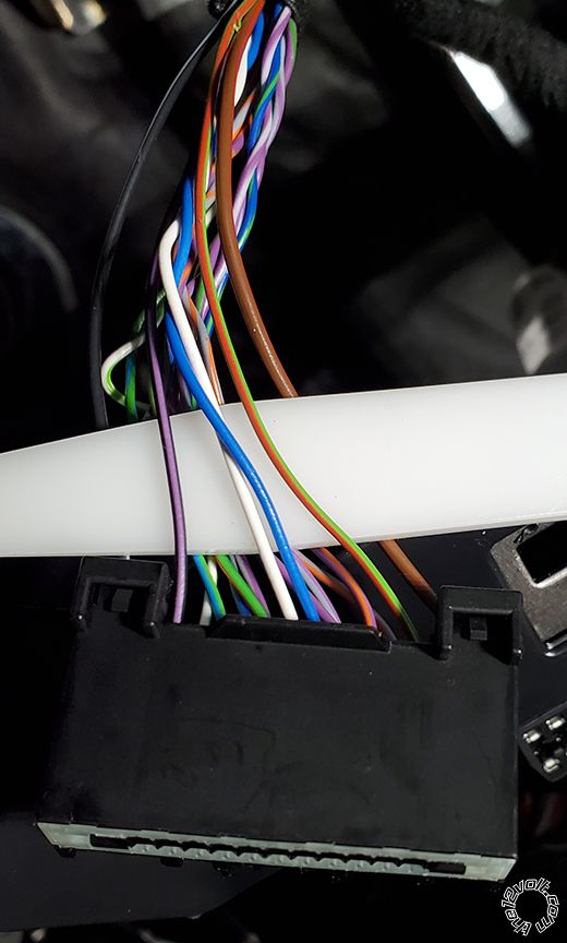
 Gateway Connector
Note: The Blue wire in this photo will be White/Blue on your truck
Gateway Connector
Note: The Blue wire in this photo will be White/Blue on your truck
 Headlamp Connector
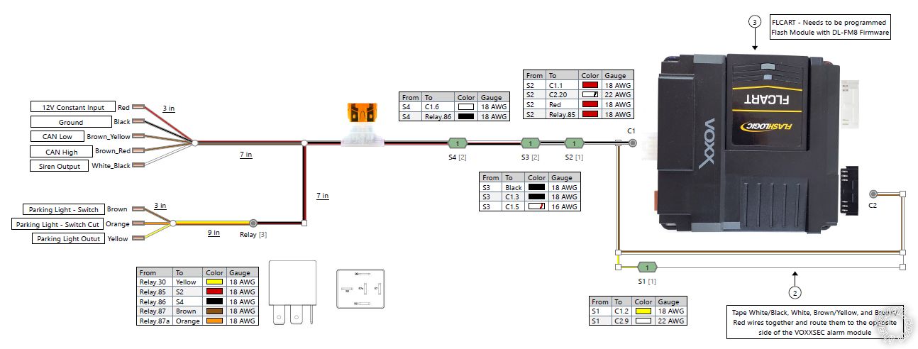
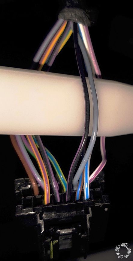 Diagram of how to prep the alarm for this application
 Printable version


