the12volt.com spacer
icon

Gentex Mirror Display Problems


Post ReplyPost New Topic
< Prev Topic Next Topic >
mr. mod 
Member - Posts: 6
Member spacespace
Joined: October 17, 2006
Location: United States
Posted: November 10, 2006 at 8:08 AM / IP Logged  

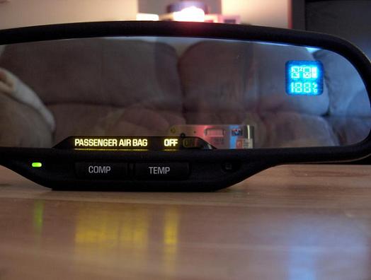
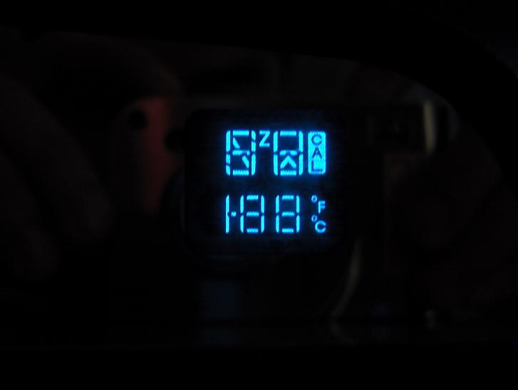
I recently worked to install on of the OEM version of Gentex mirrors in my vehicle.  When the unit was powered up, I found that the entire display would illuminate and never go to a normal display.  All other functions for programming, calibration, on / off seemed to still be working, but no matter what, every segment of the EFD stayed lit.  I stumbled on one other person who had the same problem, but unfortunately the trail never said whether the issue was fixed.  It implied that the problem was a lack of temperature probe connection in the final post.

After some frustration, I finally dug deeper into the system and found the root cause, at least in my situation.  The compass engine (remote module) connector had come out of its socket.  This likely caused the mirror to go into "error" mode and the indication was to turn the whole screen on. 

The photos below are from the original post, https://www.the12volt.com/installbay/forum_posts.asp?tid=65874&KW=gentex#reply 

Gentex Mirror Display Problems -- posted image.

Gentex Mirror Display Problems -- posted image.

The mirror consists of two electronic modules.  The main one is in the mirror housing and controls all of the mirror functions.  The second is a little PCB that is hidden beneath the black clam shell housing that is integrated into the windshield connection.  If you gently pop off the cover it will reveal the PCB which has a socket on-board and tiny mating connector.  Make sure this is fully mated (mine had pulled apart completely) and this compass module is properly oriented in the housing...orientation is important if you want the compass to work properly when you're done.  One you've reconnected this location, reassemble the housing to he mount be careful not to pinch the short supply harness.

I am posting so just in case there are more people out there that may run into the same thing you won't have to hunt quite as hard to find one definite fix.  One final note, when the temp sender is disconnected, the mirror will still work, but the temp display defaults to 0.  Hope it helps, good luck.

ron43964 
Member - Posts: 8
Member spacespace
Joined: November 18, 2006
Posted: November 18, 2006 at 8:46 PM / IP Logged  

Is this the pin out connections you used?

pin 3 air bag "on" gnd to activate

pin 4 air bag "off" gnd to activate

pin 6 temp probe sensor

pin 7 temp probe sensor

pin 8 gnd

pin 13 ign +12v

mr. mod 
Member - Posts: 6
Member spacespace
Joined: October 17, 2006
Location: United States
Posted: November 19, 2006 at 11:28 AM / IP Logged  

I did not connect the air bag lights in my installation, the photos in this posting were from a different person's install.  The mirror I installed did not have the air bag information line.  My mirror however did use the 16-pin connector.

From my install, I can confirm the power (13), ground (8), and two temp sensor connections (6 & 7) so I suspect the rest show in other's posts are correct as well.

ron43964 
Member - Posts: 8
Member spacespace
Joined: November 18, 2006
Posted: November 19, 2006 at 1:09 PM / IP Logged  

thanks for the info!

ron43964 
Member - Posts: 8
Member spacespace
Joined: November 18, 2006
Posted: November 27, 2006 at 1:12 PM / IP Logged  

mr mod,

did you do anything with pins 5 and 16?  The display on my mirror dims properly when I cover up the sensor facing the front of the vehicle, but the mirror itself doesn't appear to darken as it should.

I've looked at other posts & these two pins are identified as signals to/from LH outside mirror sensor?

mr. mod 
Member - Posts: 6
Member spacespace
Joined: October 17, 2006
Location: United States
Posted: December 01, 2006 at 3:04 AM / IP Logged  

I did not connect any additional pins, no need in my application.  I only wanted the compass, external temperature, and electrochromatic (EC) features.  The pins are only used if you also want to control external remote mirrors.  My last vehicle (99 Blazer) had this and would dim the LH external mirror in conjunction with the interior rear view.  If you don't have external EC mirrors, you do not need to do anything with these pins. 

How are you testing the mirror?  Keep in mind the front sensor is for detection of ambient light where the rearward detects headlamps behind you.  In order for the mirror dimming feature to work, the front needs to be dark (covered) as if driving at night and then the rearward needs to see light.  A flashlight directed at this one will work for test purposes.  If both conditions are not met the dimming feature will not work.

If this still doesn't work, check to make sure the green status LED is on when the mirror is on.  Depending on which Gentex mirror you have, there are press and hold button sequences that allow you to turn the EC function completely off.  If the LED is off, the mirror dimming is disabled.

Hope this helps...if not post again and I'll think some more.

ron43964 
Member - Posts: 8
Member spacespace
Joined: November 18, 2006
Posted: December 05, 2006 at 2:12 PM / IP Logged  

mr. mod

I am testing correctly.  The temp & compass readout does dim properly.  The mirror does not.  I measure about 3.1 volts between pins 5 & 16.  I'm almost certain these need to be connected to an outside side dimming mirror in order for the mirror to dim properly.  Problem is I don't have the LH outside dimmable mirror.  Did your 16 pin mirror have wires on pins 5 & 16?  I think if it did not, then that would explain why you didn't need to wire them up.  Maybe a resistor or jumper could be substituted for the outside mirror.  What do you think?

ron43964 
Member - Posts: 8
Member spacespace
Joined: November 18, 2006
Posted: December 06, 2006 at 2:35 PM / IP Logged  

I found that connecting a 10 ohm resistor between pins 5 & 16 will let the mirror dim properly.  Hope this helps someone else out.

Ron

mr. mod 
Member - Posts: 6
Member spacespace
Joined: October 17, 2006
Location: United States
Posted: December 06, 2006 at 5:41 PM / IP Logged  

Good find...makes sense.  It appears I was lucky that my mirror did not require the resistance.  Mine actually shipped with zero connecting parts so bought all the connectors, harnesses, temp sensor, etc. from a local dealership...not cheap for the "extra" parts but still better than buying the whole package from one of the online sources.

Just curious though, does your dimming feature work all the time or enable / disable with ambient light?  Mine also adjusts the brightness of the power (green) LED and the compass / temp display as ambient lighting gets lower.  In daylight, the dim feature does not work at all and the display and LED are at full brightness.

Mr. Mod. 

ron43964 
Member - Posts: 8
Member spacespace
Joined: November 18, 2006
Posted: December 06, 2006 at 7:30 PM / IP Logged  

My mirror works exactly the same as yours does.  The difference is that mine was designed to auto dim the LH outside mirror as well.  The way the mirror works is by passing a current to create the dimming action.  With pins 5 & 16 open circuited, there was no path for the current to flow, hence no dimming action.  I took apart an old auto dim rearview mirror and hooked the mirror element only in series with pins 5 & 16.  I measured the current & voltage across the element and calculated that at full dim it was about 10 ohms.  Then substituted the 10 ohm resistor for the old mirror element.  Problem solved!


Sorry, you can NOT post a reply.
This topic is closed.

  Printable version Printable version Post ReplyPost New Topic
You cannot post new topics in this forum
You cannot reply to topics in this forum
You cannot delete your posts in this forum
You cannot edit your posts in this forum
You cannot create polls in this forum
You cannot vote in polls in this forum

  •  
Search the12volt.com
Follow the12volt.com Follow the12volt.com on Facebook
Tuesday, April 23, 2024 • Copyright © 1999-2024 the12volt.com, All Rights Reserved Privacy Policy & Use of Cookies
Disclaimer: *All information on this site ( the12volt.com ) is provided "as is" without any warranty of any kind, either expressed or implied, including but not limited to fitness for a particular use. Any user assumes the entire risk as to the accuracy and use of this information. Please verify all wire colors and diagrams before applying any information.

Secured by Sectigo
the12volt.com spacer
Support the12volt.com
Top
the12volt.com spacer