Convert 12V DC to 6V DC
Printed From: the12volt.com
Forum Name: General Discussion
Forum Discription: General Mobile Electronics Questions and Answers
URL: https://www.the12volt.com/installbay/forum_posts.asp?tid=106959
Printed Date: April 06, 2026 at 7:10 PM
Topic: Convert 12V DC to 6V DC
Posted By: ezrollin
Subject: Convert 12V DC to 6V DC
Date Posted: August 22, 2008 at 3:29 PM
how do you change 12v DC to 6v DC? what resistor or potentiometer would that require?
Would a voltage regulator work? (where would I find one?) what would be your guess at a normal average sized car battery's current? current is measured in amp-hours correct? so how many amp-hours? how much wattage does it put out? sorry I didnt look it up on my own (or am too retarded to do so) Thanks Alot!
Replies:
Posted By: megaman
Date Posted: August 22, 2008 at 3:47 PM
what are you attempting to do?
Posted By: ezrollin
Date Posted: August 22, 2008 at 3:51 PM
I'm just trying to change 12v dc from my motorcycles battery to a 6v DC input on my bike's computer. My bike will not work without this 6v DC input Thanks alot!
Posted By: KPierson
Date Posted: August 22, 2008 at 3:54 PM
If you need a power supply a resistor won't work, if you need a voltage reference you can go that route. They make an adjustable voltage regulator, an LM317. You control the output voltage by selecting a few external components (there are calculators available on the net to help with this). An LM317 should get you about 1 amp of power. All car batteries are different and it would be pointless to design something off the "average" storage capacity of all car batteries. You should be able to take the make and model of your battery and find out how much reserve capacity it has. ------------- Kevin Pierson
Posted By: ezrollin
Date Posted: August 22, 2008 at 4:27 PM
lets just assume my motorcycle battery is... 600 cold cranking amps. how much watts could it produce? what would be the Amp-Hour? reserve? I will get my battery's exact stats tomorrow. Will try to order one of those LM317s but it would be cooler if I could just make one out of resistors Last night I metered my battery, it was at 12.59 Volts, I hooked up 20x 100Ohm resistors and got my voltage down to 11.99V. I'm sure with enough or the right kinds of resistors I could get 12v DC down to 6v DC. thanks alot!
Posted By: ezrollin
Date Posted: August 22, 2008 at 4:36 PM
ezrollin wrote:
Last night I metered my battery, it was at 12.59 Volts, I hooked up 20x 100Ohm resistors and got my voltage down to 11.99V. I'm sure with enough or the right kinds of resistors I could get 12v DC down to 6v DC.
by that logic it would take me 200 more of those 100 ohm resistors to arrive at around ~5.99V Is my logic flawed?
Posted By: KPierson
Date Posted: August 22, 2008 at 4:54 PM
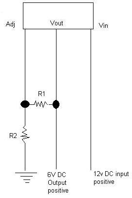
Resistors resist current, not voltage. If you took two 100 ohm resistors and wires them in series (one end to the other) then connected them to the battery you'll end up with almost 6vdc exactly if you measure from the middle of the two resistors to ground (a standard voltage divider circuit). However, you'll have basically no current at all to power anything, and as you load the circuit the voltage will start to drift. You could take the voltage divider circuit and add a couple transistors to it to increase current capacity, but why not just buy a voltage regulator and be done with it? Also CCA isn't what you need, you need reserve capacity. ------------- Kevin Pierson
Posted By: ezrollin
Date Posted: August 22, 2008 at 5:47 PM
[QUOTE] https://en.wikipedia.org/wiki/Series_and_parallel_circuits#Series_circuits To find the voltage across a component with resistance Ri, use Ohm's law again: <_i \,</math> where I is the current, as calculated above. The components divide the voltage according to their resistances, so, in the case of two resistors, V1 = R1 V2 = R2 [/QUOTE] How come when I connect 20 100ohm resistors end to end (using a 12v dc battery) I end up with 11.99Volts? thanks alot for the info!!
Posted By: KPierson
Date Posted: August 22, 2008 at 6:03 PM
Where are you measuring voltage from?
-------------
Kevin Pierson
Posted By: ezrollin
Date Posted: August 22, 2008 at 6:24 PM
KPierson wrote:
Resistors resist current, not voltage. If you took two 100 ohm resistors and wires them in series (one end to the other) then connected them to the battery you'll end up with almost 6vdc exactly if you measure from the middle of the two resistors to ground (a standard voltage divider circuit).
I guess I'm not understanding, (sorry if it seemed like I wasnt listening to you) is there any way you could make a quick Paint drawing? I hook negative voltage meter to negative battery post. I hook resistors to battery positive then voltage meter positive to the last resistor.
(if that makes sense? I can make a quick paint drawing no problem!) I really wanna get the voltage Regulator!
Posted By: ezrollin
Date Posted: August 22, 2008 at 7:14 PM
I hook negative voltage meter to negative battery post. I hook resistors to battery positive then voltage meter positive to the last resistor. 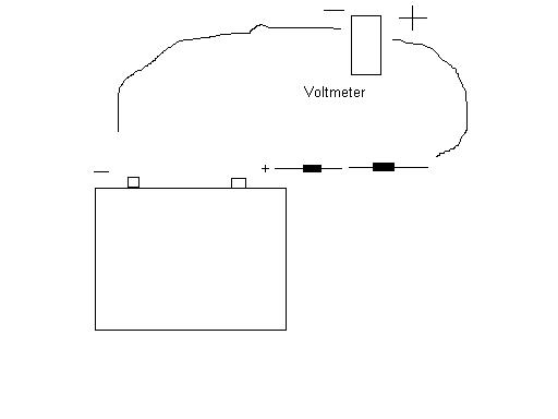
I hear you saying that resistors dont resist voltage but resist Current (amps) instead. I just dont understand why and how you came up with the 6v using 2 resistors (when it resists current instead of voltage)? thanks again!!
Posted By: megaman
Date Posted: August 22, 2008 at 7:38 PM
first of all your diagram shows the voltmeter in series with the circuit. This means that you have almost no understand of basic electronic principles. Please do not attempt to build a circuit. No need to get all huffed up about not knowing basic electronics, I have no idea how to make a cake and that is pretty simple.. so I'm told. Here's your proper voltage divider diagram which WILL NOT WORK in your scenario as it doesn't supply the necessary current for your application, and for a host of other reasons. 
Posted By: ezrollin
Date Posted: August 22, 2008 at 8:01 PM
wow, are you an electrician or an artist? very nice! thanks alot!
Posted By: i am an idiot
Date Posted: August 22, 2008 at 8:41 PM
ezrollin wrote:
I hook negative voltage meter to negative battery post. I hook resistors to battery positive then voltage meter positive to the last resistor.
I hear you saying that resistors dont resist voltage but resist Current (amps) instead. I just dont understand why and how you came up with the 6v using 2 resistors (when it resists current instead of voltage)? thanks again!!
If you connect the above circuit, the meter will read 12 volts. The reason for this is there is no current going through the circuit. The input impedance of your meter is phenominally high. The resistors will drop voltage, but it is dependent on current. No current draw, no voltage drop. The reason you can use a resistor to drop voltage for an LED or a light bulb, (things that do not vary in current draw) is that they pull a given amount of current, you can adjust the value of the resistor to get the appropriate amount of voltage drop, to power the lamp or LED. The reason you can not use a resistor to drop voltage on a pump (or anything electromechanical) is that when it is not under a load, it will not pull as much current as it does when under a load. So when you need the pump most, it will not be getting enough voltage to operate.
Posted By: ezrollin
Date Posted: August 22, 2008 at 9:35 PM
thanks alot guys! very informative! It looks like I'm dumber than I thought. you can keep the info coming if you want! Looks like I have no other choice but to buy the voltage regulator (which is fine, would love to have several) On my motorcycle my key lock cylinder has failed. When I turn my key to run I get NO lights whatsoever. 12v goes into my key lock cylinder and when the correct key is inserted the key lock cylinder is supposed to spit out 6v DC which goes to my computer (to allow it to run). I'm trying to bypass my key lock cylinder. I have no problems posting the title to my bike or whatever you want. Much appreciated!
Posted By: i am an idiot
Date Posted: August 22, 2008 at 9:53 PM
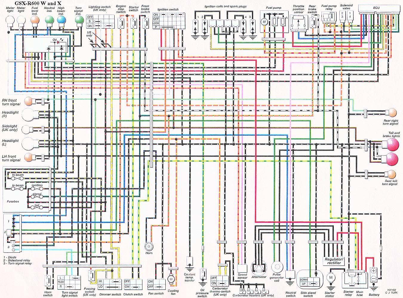
What kind of bike is this? I have heard of the same Hocus Pocus on a GSXR, but several are for sale on the internet with Remote start units installed. I found a diagram of the GSXR and there is nothing of the sort on the bike. They say the ECU is looking for 9 volts on that bike, according to the diagram, the ignition switch provides a ground for the ECU the Magic Regulator is inline with the power wire of the ECU.
Posted By: i am an idiot
Date Posted: August 22, 2008 at 10:02 PM
I still have no idea what kind of Bike you have, here is the diagram for the GSXR Ignition switch is in center of page at top. ECU is at top all the way to the right. This bike too is supposed to have some magic in the key. Notice the right side of the ignition switch simply connects the orange wire from the ECU to ground. The ECU may only run on 9 volts as they say, but if it does, the regulation is in the power side of the unit. The orange wire is simply looking for ground to allow it to turn on. https://smokeriders.com/diagrams/Suzuki/Four-Strokes/GSX-R600/GSX-R600_W_and_%20X_.jpg
Posted By: ezrollin
Date Posted: August 22, 2008 at 10:05 PM
sorry about that delay Its a 2001 Kawasaki Ninja 750 P model (carbs) clean & clear title Paid $3500 from some sort of lawyer guy in dallas
Posted By: ezrollin
Date Posted: August 22, 2008 at 10:14 PM
That has no load... it would get really hot and might explode the battery. Am I remotely correct?
Posted By: i am an idiot
Date Posted: August 22, 2008 at 10:28 PM
Not gonna blow up or heat up as long as the resistors are 1 watt or larger. The circuit will need to handle 3/4 of a watt.
OHM'S LAW
BASE FORMULAS P=I*E E=I*R
TO FIND VOLTAGE E=P/I E=I*R E=SQR(P*R)
TO FIND CURRENT I=P/E I=E/R I=SQR(P/R)
TO FIND POWER P=I*E P=E2/R P=I2*R
TO FIND RESISTANCE R=E2/P R=E/I R=P/I2
P = Power in Watts
E = Electromotive Force in Volts
I = Electrical Current in Amps
R = Electrical Resistance in Ohms
SQR = Square Root
Note:
I use 'E' to represent voltage most of the time but sometimes you'll see 'V' used for voltage. Don't let it confuse you.
Copied and Pasted with permission form BCAE1.com
Posted By: i am an idiot
Date Posted: August 22, 2008 at 10:41 PM
Is there any way you could use a volt meter and check voltage on every wire of the ignition harness? Ground the black meter lead to ground, turn the key on and read the DC voltage of every wire on the harness. Post them here.
Posted By: ezrollin
Date Posted: August 22, 2008 at 11:15 PM
Posted By: KPierson
Date Posted: August 23, 2008 at 11:19 AM
I would just pick one up at radioshack along with the resistors that you need. Do you have any idea what this voltage is used for? Is it only to tell the ECU that the correct key has been inserted (like an immobilizer)? If you only need it as a reference voltage you should be able to use a pot, but like I said before if you are actually powering circuits you will need a power supply. ------------- Kevin Pierson
Posted By: ezrollin
Date Posted: August 23, 2008 at 3:04 PM
KPierson wrote:
I would just pick one up at radioshack along with the resistors that you need. Do you have any idea what this voltage is used for? Is it only to tell the ECU that the correct key has been inserted (like an immobilizer)? If you only need it as a reference voltage you should be able to use a pot, but like I said before if you are actually powering circuits you will need a power supply.
I tried playing around with a potentiometer yesterday but couldnt get any voltage drop. It was a 5k ohm on a 12v dc batt. Again, I'm sure I was doing something wrong (but I've had pots work for me before.. idk whats the problem?) I bought a LM317 T Positive (adjustable voltage reg) from Radio Shack today. What resistors would I need? Stats: TO-220 Case Internal current-limiting protection Vout adjustable +1.2 to 37v (YEAY!) Cout limited to 1.5A Absolute Maximum ratings: Power dissipation: 15W Input-Output voltage differential: 40V ???? whatever happened to +1.2 to 37V? Shouldnt it be 35.8V difference? Load regulation (typ.): 0.1% / V Fine regulation (typ.) 0.01% / V Ripple rejection (typ.): 80dB all ratings assume proper heatsinking
Posted By: KPierson
Date Posted: August 23, 2008 at 3:21 PM
Do a google search for LM317 calculator, there are several sites out there with working calculators. To use a pot as an adj voltage device you need to apply power to one outside pin, apply ground to the other outside pin, and use the middle pin (the wiper) as your voltage output. If you try to use only two pins you won't get any voltage drop. The 1.2v - 37v spec is the OUTPUT. The input-output differential of 40vdc says that your INPUT voltage must be within 40vdc of the output voltage - for example if you want 6vdc out your input voltage must be below 46vdc. ------------- Kevin Pierson
Posted By: ezrollin
Date Posted: August 23, 2008 at 3:46 PM
you guys are the shiznit!! Thanks ALOT!!!!
Posted By: ezrollin
Date Posted: August 23, 2008 at 6:42 PM
So I dont need or Have to have any capacitors at all, correct? Yes, my bike's ECU needs a ~6V DC refrence voltage! 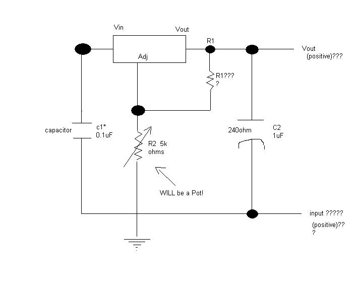
Posted By: ezrollin
Date Posted: August 23, 2008 at 6:56 PM
I'm just confused where it says C2 they have it set as 240 ohms with a capacitor.... Is this where my Resistor1 goes or should I put my Resistor1 where I marked it as R1?????? 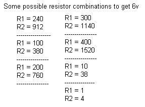
Posted By: ezrollin
Date Posted: August 23, 2008 at 7:15 PM
I see where the input goes now. duh!!! sorry It says on R2 that it needs a variable resistor (symbol) does it really mean a Pot?
Posted By: i am an idiot
Date Posted: August 23, 2008 at 7:24 PM
I can not find any info to support the 6 volts to trigger the ECU. Where did you read or hear of that? Are the wire colors coming from the Ignition switch, Brown, White, Grey, Blue, Red, White again, and ORANGE / Green? https://www.zx-6r.com/downloads/wiring_diagrams.shtml
Posted By: ezrollin
Date Posted: August 23, 2008 at 7:49 PM
Would this be a simpler dumbed down version that would work instead? THANKS!
Posted By: reax222
Date Posted: August 23, 2008 at 7:56 PM
megaman wrote:
first of all your diagram shows the voltmeter in series with the circuit. This means that you have almost no understand of basic electronic principles. Please do not attempt to build a circuit. No need to get all huffed up about not knowing basic electronics, I have no idea how to make a cake and that is pretty simple.. so I'm told.
Here's your proper voltage divider diagram which WILL NOT WORK in your scenario as it doesn't supply the necessary current for your application, and for a host of other reasons.
Just for my review. This diagram shows a total amperage of 0.06a. Kirschoff says the voltage across either resistor is 6v.
Now if both resistors were 1ohm and could handle 72 watts you could get 6 amps? If the resistors were 6ohm you could get 1 amp across each resistor?
Posted By: ezrollin
Date Posted: August 23, 2008 at 8:33 PM

Never mind, I will follow this one!!!! yeay
Posted By: ezrollin
Date Posted: August 24, 2008 at 6:35 PM
i am an idiot wrote:
I can not find any info to support the 6 volts to trigger the ECU. Where did you read or hear of that? Are the wire colors coming from the Ignition switch, Brown, White, Grey, Blue, Red, White again, and ORANGE / Green? https://www.zx-6r.com/downloads/wiring_diagrams.shtml
Sorry I didnt reply! Its called the Logic Supply Voltage to the ECU yes, there is a brown, white, GREY ( 6v ), blue, red red and blue are for lights sorry, my manual is on my other computer.. I will have to whip that out for you!!
Posted By: i am an idiot
Date Posted: August 24, 2008 at 6:40 PM
No need to get the manual for me, As long as you have documentation or heard of it from a reputable source, that is fine. I just didn't want to help you chase your tail. Are you familiar with the GM keys that had the resistor blister at the top end of the key? Does your key have a similar blister?
Posted By: ezrollin
Date Posted: August 24, 2008 at 8:56 PM
never heard of a resistor blister. I have a 2002 gm car and I have a resistor in my key... some people call it a "chip". Its like 18k ohms... I cant remember where I read that. Are we talking about the same thing? My key does not have any form of electrical in it (except for being conductive  )
Posted By: i am an idiot
Date Posted: August 24, 2008 at 9:04 PM
Yes the 18K resistor is what I am talking about. It is not a chip, it's only a resistor. You did verify that there was only 6 volts on the grey wire coming from the ignition switch?
Posted By: ezrollin
Date Posted: August 25, 2008 at 4:14 PM
I was making fun of people calling it a "chip" sorry I have not yet metered the 6v input grey wire (or I have and got nothing). I just heard from a reputable source that its a 6v dc input to the ecu. (6v output from the key lock cylinder) What wattage should my resistors be? I got my R1 Resistor to 1315 ohms and my R2 pot is a 5k ohm. (which should equal 6v) but gives me a MAX of 4.98V So instead I go against the math and use 1090 ohms on R1 and 5k on ohm to which should get me ~6.98v but instead gives me a max of 5.96volts wierd... wish i had the option to turn it up to around 6.10v ohh well we'll try this
Posted By: ezrollin
Date Posted: August 25, 2008 at 5:05 PM
Here is my wiring topography. My resistors are a mix of 1 watt and 1/2 watts - is this okay?
Posted By: i am an idiot
Date Posted: August 25, 2008 at 5:29 PM
You should only be using 2 connections of the potentiometer. You are simply using it as a variable resistor. connect the middle leg of the pot to the negative terminal of the battery. You should get output from the output terminal of the regulator. Leave the resistor connected there too. Just connect another wire there to run to the ignition switch. The right terminal of the pot should be open.
Posted By: ezrollin
Date Posted: August 25, 2008 at 6:57 PM
i am an idiot wrote:
You should only be using 2 connections of the potentiometer. You are simply using it as a variable resistor. connect the middle leg of the pot to the negative terminal of the battery. You should get output from the output terminal of the regulator. Leave the resistor connected there too. Just connect another wire there to run to the ignition switch. The right terminal of the pot should be open.
For my Pot you said: middle leg = negative on battery (ground) right leg = open? unused? left leg = ???? sorry
Posted By: ezrollin
Date Posted: August 25, 2008 at 7:16 PM
I bet its the adjuster (com) that makes sense
Posted By: 04nata
Date Posted: August 25, 2008 at 7:27 PM
couldn't he just go to Radio Shack and get a converter and wire it in?
Posted By: i am an idiot
Date Posted: August 25, 2008 at 7:30 PM
Leave the left leg just as it was. I gave instructions to repair it. Just connect middle leg to battery ground. And add the wire to go to the ignition. Remove wire from right leg of pot.
Posted By: ezrollin
Date Posted: August 25, 2008 at 7:40 PM
i am an idiot wrote:
Leave the left leg just as it was. I gave instructions to repair it. Just connect middle leg to battery ground. And add the wire to go to the ignition. Remove wire from right leg of pot.
I'm sorry which wire are you talking about? The middle pot wire goes to ignition AND battery negative / ground?
Posted By: ezrollin
Date Posted: August 25, 2008 at 8:06 PM
this is how I think you're explaining it to me... sorry I'm confused This gives me a Max of 5.44v DC out. ( with R1 hooked up Or Not! ) thanks alot!
Posted By: i am an idiot
Date Posted: August 25, 2008 at 8:06 PM
Middle wire of pot goes only to ground. Output leg of the 317 remains connected to the resistor in your picture. You also need to connect a wire to the output of the 317 to run to the grey wire. The output of the 317 will be connected to the resistor and to the wire going to the grey wire.
Posted By: i am an idiot
Date Posted: August 25, 2008 at 8:12 PM
Posted By: ezrollin
Date Posted: August 25, 2008 at 8:20 PM
thats BEAUTIFUL!!! thanks ALOT!!! Awesome voltage positions!! 1.243V - 6.22V AWESOME!!!
Posted By: hallablack
Date Posted: June 13, 2009 at 1:31 PM
just want to say thanks for the wire diagram on the GSXR 600 man i was lookin all over for it and could not find the right one so hopefully i can get started so i can ride 2night, but once again thanks your a bike saver.
-------------
Halla Black at cha
Posted By: howie ll
Date Posted: June 13, 2009 at 4:47 PM
Sorry, I've come in at the end but 600CCA? You could start a small truck with that.
|