wire to fuel pump wire, fuse gets very hot
Printed From: the12volt.com
Forum Name: General Discussion
Forum Discription: General Mobile Electronics Questions and Answers
URL: https://www.the12volt.com/installbay/forum_posts.asp?tid=115884
Printed Date: May 13, 2026 at 10:17 AM
Topic: wire to fuel pump wire, fuse gets very hot
Posted By: kmn5
Subject: wire to fuel pump wire, fuse gets very hot
Date Posted: August 24, 2009 at 7:58 PM
I rewired my fuel pump to pull power direct from the battery via a relay And in between the relay and the battery I have a 12 gauge wire fuse holder and the section between the fuse and the battery gets very hot (yellow/red wire)the fuse holder is very hot too
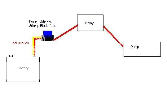
the wire before and after the fuse are the exact same gauge
the wire leading from the fuse to the relay is cold... odd, right?
What can I do to fix this?
I haven't found any blade fuse holders with wires that are 8 gauge or bigger
I was thinking of the stereo tube fuse holders
What do you guys use?? 
then I can use a 8 gauge wire
what do you guys think?
Replies:
Posted By: i am an idiot
Date Posted: August 24, 2009 at 8:21 PM
Make sure the connection to the battery is crimped tightly, and make sure the fuse fits tightly on the left side of the fuse holder. If it is loose, using a pair of pliers or a vice, with the fuse out of the holder, squeeze the holder to make the fuse fit tighter. Resistance = Heat. Since the wire on the other side of the fuse holder is the same size, there has to be a bad connection in one of the 2 mentioned locations.
-------------
Let's Go Brandon Brown. Congratulations on your first Xfinity Series Win. LGBFJB
Posted By: kmn5
Date Posted: August 24, 2009 at 8:26 PM
i am an idiot wrote:
Make sure the connection to the battery is crimped tightly, and make sure the fuse fits tightly on the left side of the fuse holder. If it is loose, using a pair of pliers or a vice, with the fuse out of the holder, squeeze the holder to make the fuse fit tighter. Resistance = Heat. Since the wire on the other side of the fuse holder is the same size, there has to be a bad connection in one of the 2 mentioned locations.
Thanks!
this is the best answer I've gotten
(from the other forums, people have only suggested going to bigger wires, or shorter wire... yea that last one didn't make sense to me either)
Posted By: t&t tech
Date Posted: August 26, 2009 at 9:32 PM
He is an absolutely brilliant fellow isn't he! I'm sure you would have never thought had you judged by his name! . . Cheers, Mr idiot, i read that piece of info a long time ago from you, it has clarified alot of small issues i've encountered during the brief time i've been installing. I must say thank you even though it wasn't directed to me! -------------
Posted By: tommy...
Date Posted: August 26, 2009 at 10:16 PM
I see those blade fuse holders do that quite often...I would recommend just to replace the fuse/fuseholder w/ maybe a mini-anl fuse and fuse holder...Stay away from the glass tube holders and fuses(agu)...Normally the solder in the tips of those glass fuses where the rod meets the cap in the inside of the fuse has the same issue and melts the fuse holder and eventually ruins the fuse...Maybe w/ a lower current draw the AGU fuse holder would be OK ...?Just what i have experienced....Bussman is a good company...! And of course you could always squeeze the female spades in the inside of your current holder...Be sure to look at the condition of the female spade in the holder also...Is it charred and lost its coating...? Another reason to replace if it is... Oh and if it is the connection at the battery...Dis-regaurd above...: )
-------------
M.E.C.P & First-Class
Go slow and drink lots of water...Procrastinators' Unite...Tomorrow!
Posted By: kmn5
Date Posted: August 26, 2009 at 11:11 PM
Just an update
I put in one of these distribution block/fuse holders

uses mini anl fuses
(I bought this years ago, but forgot all about it and finally put it to use)
also wired in my amp and carputer
which cleaned up a bit of the wiring
Ran the car for 30 mins, and wire is ambient temp :)
Thanks guys!
Posted By: tommy...
Date Posted: August 26, 2009 at 11:22 PM
I cant help it...Every time i see a problem solved...All i see is the captain...Should end every complete post w/ it...! Glad everything worked well...And glad you got to use the dist block/fuseholder...Just make sure everything is tight,tight,tight...! ------------- M.E.C.P & First-Class
Go slow and drink lots of water...Procrastinators' Unite...Tomorrow!
Posted By: i am an idiot
Date Posted: August 27, 2009 at 12:47 AM

And it looks as though it recieved The12Volt.com's seal of approval between my computer and the server. ------------- Let's Go Brandon Brown. Congratulations on your first Xfinity Series Win. LGBFJB
Posted By: angelmeza310
Date Posted: February 10, 2010 at 9:27 PM
Kim---- can you do this same operation for a 94 cadillac fleetwood???
-------------
Fire310
Posted By: tommy...
Date Posted: February 10, 2010 at 9:50 PM
edit... ------------- M.E.C.P & First-Class
Go slow and drink lots of water...Procrastinators' Unite...Tomorrow!
Posted By: angelmeza310
Date Posted: February 10, 2010 at 9:56 PM
rewired my fuel pump to pull power direct from the battery via a relay? ------------- Fire310
Posted By: oldspark
Date Posted: February 11, 2010 at 1:20 AM
For Pete's sake - connect them properly.
The fuel pump relay needs to be controlled by the ECU, else an "engine running" circuit like charge sensing, air flap, or ignition (spark) sensing etc.
This is to ensure the pump STOPS in an accident etc - ie, ignition on, fuel line severed etc.
Charge controlled is the most common and easiest - eg:

(Thanks to Tezza)
....where Reg means the charge lamp aka D+ or L wire from the alternator (else its regulator), and Start is the starter-motor's +12V from the ignition key to "prime" the system.
[If the alternator or regulator fails, just disconnect the D+ or L wire and the relay should turn on so that you can limp home.]
(The above fig is from the last post at the12volt.com/installbay/forum_posts.asp?tid=107789.)
And DO NOT use oil pressure signals for fuel pumps - that went out with draining carbies and stiffening capacitors. 
But there are many variants of the above circuit including manual bypass & prime (aka - milking the tank), or using an SPST relay and diode connecting the various inputs (Starter, Charge, air-flap, bypass).
Posted By: almeida.kodi
Date Posted: February 27, 2010 at 7:10 PM
Kmn5-
In the future if you run across any similar type problem with extensive heat in any circuit run a simple voltage test right off the rip. If you were to test the circuit you wired for your fuel pump disconnect the feed to the pump (at the pump) and arrange your relay input and output to be normally closed therefore allowing voltage to be applied without it being energized while still using the contacts in the relay for the test. Connect your voltmeter to the battery and the the end of the wire feeding your fuel pump. Any difference in potential from the battery to the end of your feed will be displayed on your meter. Lets say it read 1 volt, you now know that even with the load disconnected you are dropping a volt somewhere in the circuit which means there is resistance and resistance will induce heat. Also if the battery is too far away from the feed use 2 calibrated meters testing each 12 volt signal to ground and subtract the difference giving you the same number of dropped voltage as the first test. Once you have figured out how much voltage you are dropping unintentionally break the circuit in as many places as you can and use an ohmmeter to do the rest. write down the resistance read in each portion of the circuit and use ohms law to figure out how much voltage drop is normal for each. If there is actually an abnormality in the circuit you will be able to find it very quickly. everything should read almost a direct short so you should not have a problem identifying the issue.
Although "crushing the fuse holder" haha sounds like a very quick fix for this issue it is not the right answer. troubleshooting is very important. If you have an electrical issue unplugging and plugging it back in different configurations until it works is not a professional way to do things. As a rule of thumb if your circuit was intended to pull 30 amps you need to use at least a 10 AWG conductor. All those guys that told you that when you first posted this problem were right. When you installed a giant fuse block on a 30 amp circuit all you did was introduce a heat sink to dissipate the heat generated by faulty wiring. I professionally recommend to you that you replace your conductors with the correct rated AWG standard and you will never burn down your vehicle. In no way should a 30 amp circuit need a fuse block to operate properly. You still have an issue but with a bandage on it. Good luck to you and if you have any more issues and would like the correct answer and not some mickey mouse backyard tips feel free to contact me.
-------------
Kodi H. Almeida
Posted By: tommy...
Date Posted: February 27, 2010 at 7:38 PM
almeida.kodi wrote:
Kmn5-
In the future if you run across any similar type problem with extensive heat in any circuit run a simple voltage test right off the rip. If you were to test the circuit you wired for your fuel pump disconnect the feed to the pump (at the pump) and arrange your relay input and output to be normally closed therefore allowing voltage to be applied without it being energized while still using the contacts in the relay for the test. Connect your voltmeter to the battery and the the end of the wire feeding your fuel pump. Any difference in potential from the battery to the end of your feed will be displayed on your meter. Lets say it read 1 volt, you now know that even with the load disconnected you are dropping a volt somewhere in the circuit which means there is resistance and resistance will induce heat. Also if the battery is too far away from the feed use 2 calibrated meters testing each 12 volt signal to ground and subtract the difference giving you the same number of dropped voltage as the first test. Once you have figured out how much voltage you are dropping unintentionally break the circuit in as many places as you can and use an ohmmeter to do the rest. write down the resistance read in each portion of the circuit and use ohms law to figure out how much voltage drop is normal for each. If there is actually an abnormality in the circuit you will be able to find it very quickly. everything should read almost a direct short so you should not have a problem identifying the issue.
Although "crushing the fuse holder" haha sounds like a very quick fix for this issue it is not the right answer. troubleshooting is very important. If you have an electrical issue unplugging and plugging it back in different configurations until it works is not a professional way to do things. As a rule of thumb if your circuit was intended to pull 30 amps you need to use at least a 10 AWG conductor. All those guys that told you that when you first posted this problem were right. When you installed a giant fuse block on a 30 amp circuit all you did was introduce a heat sink to dissipate the heat generated by faulty wiring. I professionally recommend to you that you replace your conductors with the correct rated AWG standard and you will never burn down your vehicle. In no way should a 30 amp circuit need a fuse block to operate properly. You still have an issue but with a bandage on it. Good luck to you and if you have any more issues and would like the correct answer and not some mickey mouse backyard tips feel free to contact me.
"Them is fighting words"...Aren't they...? ------------- M.E.C.P & First-Class
Go slow and drink lots of water...Procrastinators' Unite...Tomorrow!
Posted By: tommy...
Date Posted: February 27, 2010 at 7:47 PM
So are you saying it was NOT a faulty fuse holder...Rather something else...!? ( I gave up reading your post) Who mentioned to upgrade the wire...? Such an old post...So many people currently that need help and this was your first post...? How did you single out this post...?
-------------
M.E.C.P & First-Class
Go slow and drink lots of water...Procrastinators' Unite...Tomorrow!
Posted By: i am an idiot
Date Posted: February 27, 2010 at 9:13 PM
Wow, I didn't realise you could experience a voltage drop with ablolutely no current traveling through the wire. No load on the wire = no current draw. No current draw = ZERO voltage drop. M-I-C-K-E-Y M-O-U-S-E Mickey Mouse.
Posted By: oldspark
Date Posted: February 27, 2010 at 10:37 PM
Well there you go Idiot (Sir...) - we learn something every day!
Kodi should have added "assuming power at the pump" else test that first...
I know that is obvious to some, but after having a qualified mechanic unable to test electric fuel pumps (despite my suggestions - like a battery at each of its terminals (after disconnecting etc)) thereby causing me 4 hours of grief pulling the pumps from my spare vehicle - only to find out later "it wasn't the pumps"....
Mind you, a mechanic that works on an EFI vehicle and doesn't even have a test light.... Misses the bad battery fuselinks (that I forewarned 3 months earlier).... And blows up the EFI ECU through his repeated testing....
But at least he was qualified.
(I call him "Mechanic" because you beat him to his name. Reminds me of why golf is called golf.)
PS - small world - last night a colleague dragged up an old "unbelievably moronic" post about controlling fuel pump relays. I guess now well read about (Bosch) alternators being self-exciting too....?
Posted By: almeida.kodi
Date Posted: February 27, 2010 at 11:17 PM
well mr idiot. i will explain this once since u thought it would be funny to try and insult me. if you apply a 12 volt signal to wire and add a resistor in the middle of that wire you will be able to test before the resistor and after the resistor with no ground hooked up and you will have dropped voltage across the resistor. you will not drop all of the voltage because you are not hooked up to a ground providing a path for current. if you hooked up the ground with a single resistor in place you would drop all of your voltage across the resistor being that it would be acting like a load. since you have disconnected the ground all you will read is the voltage dropped from the resistor due to its resistance properties. all you are measuring is the potential of voltage. no one said anything about current.ask yourself do you need a ground hooked up to read voltage? the answer is no. all you need is a difference in potential from ground to positive. they don't need to be connected. simply put lets say you hook up a wire and test it at the source (battery terminal) you tread 12 volts then you go 100 feet down the wire and test again. you will still read 12 volts. a wire although it is a conductor still has resistance so that means that with your theory that there would be no way to test voltage except at the terminal unless ground is hooked up. voltage dropped across a load to create work is different than voltage dropped because of high resistance in a conductor.and as for you old sparky you jumped on the band wagon with idiot and now you seem to be just as electrically uneducated.
-------------
Kodi H. Almeida
Posted By: almeida.kodi
Date Posted: February 27, 2010 at 11:25 PM
you can give up reading it all you want my tommy but that doesn't change the fact that there is a right way and a wrong way to do things. if you read the original post kmn5 states that other forums guys were telling him to upgrade the wire and they were right. although replacing the fuse holder may have bandaged the problem it is not the right answer. if he is pulling 30 amps on that circuit 12 guage wire will not hold up forever. end of story. although i am new to all of this 12 volt install stuff I have been to school for electronics/electricity not just a book and a test and I assure you there is only one right way. electricity can cause problems and alot of damage and unless one knows the right way to do it they do not need to be doing it at all.
-------------
Kodi H. Almeida
Posted By: almeida.kodi
Date Posted: February 27, 2010 at 11:28 PM
wheres the captain now mr idiot?
-------------
Kodi H. Almeida
Posted By: i am an idiot
Date Posted: February 27, 2010 at 11:45 PM
Sometimes all I can say is WOW, this is one of those times. ------------- Let's Go Brandon Brown. Congratulations on your first Xfinity Series Win. LGBFJB
Posted By: oldspark
Date Posted: February 27, 2010 at 11:49 PM
POST EDIT - due to multiple "Message Not Posted" msgs, I got in after the above Replly. Damn again!
/end POST EDIT/
Caption not needed.
Many will find no voltage drop using the technique you specified.
Hence your information will not help them.
Mr Idiot was pointing out why many will find zero voltage drop.
The above being your first post at 12Volt, you may not realise the breadth of its audience. For example, I no longer suggest tipping the flattery upside-down to extract more power (it was a VW beetle too - all over the back seat...).
I too took some time to adjust to experts' humour - like big caps melting a battery.
Hence my last reply....
But if you call others Mickey, make sure you can take it too.
And if the mickey was taken by the wrong person due to ambiguity, well hey, you may be more careful next time. Or even read the rules....
Otherwise your tip is fine. I spent pages trying to explain to some lard that that was the best thing for his big-audio voltage drop problem. But I think he just got the bigger alternator or AGM battery anyhow... LOL! To think I didn't even insult THAT moron....! Damned rules!
Posted By: i am an idiot
Date Posted: February 27, 2010 at 11:55 PM
Let me rephrase one thing. There will be a voltage difference if you compare the readings from before the resistor to the reading you get after the resistor. There will be current through the resistor, the meter you use to test will have probably around 10,000 ohms. Depending on the value of your resistor, you may see a slight difference in voltage. 100 ohm resistor, no difference. A 1Meg ohm resistor, you will see a difference. But there is current going through it. The resistance of the meter.
-------------
Let's Go Brandon Brown. Congratulations on your first Xfinity Series Win. LGBFJB
Posted By: t&t tech
Date Posted: March 01, 2010 at 6:06 PM
Mr kodi, aren't you new around here? We never said you didn't know it all, but geez, you don't have to be so frank about it! Secondly Mr Idiot was spot on and solved the OP's problem immediately! If you knew anything you would have been able to figure out that if the gauge of the wire was inadequate the problem would have persisted, but it didn't, so why make yourself a fool over it! The guys who have contributed to this post have been around this site and in this field for years, their experience in this field gives them the ability to back up whatever conclusions they draw , i have personally learnt from them and continue learning! Thirldy this is a very well renowned site, and people come here to acquire quick solutions to their problems from real pros, and they always do! This isn't a place to bash people and argue, especially when you know nothing of the things that go on around here, from your first post it seems you aren't even capable of giving advice, (wondering why?), simple, you tried to make it sound too complicated, (but then again, that's what people do when they can't seem to find away to make themselves seem like they knew it all)! Welcome to the fourums by the way  -------------
Posted By: tommy...
Date Posted: March 01, 2010 at 6:21 PM
I had a whole new(less graphic) rant...But you basically said it...CHEERS...! (last post was deleted...probably rightfully so...)
-------------
M.E.C.P & First-Class
Go slow and drink lots of water...Procrastinators' Unite...Tomorrow!
Posted By: t&t tech
Date Posted: March 01, 2010 at 7:52 PM
I'll drink to that! (non alcoholic beverage preferrably), Cheers Tommy, Mr Idiot and Oldspark! -------------
Posted By: howie ll
Date Posted: March 05, 2010 at 4:51 PM
Trouble is I think everyone bar Peter the old sparker missed this one, is this set up safe?.
Kodi...if it works, it's the right answer. I'm using the sealed DEI fuse holders all with 30amp circuits from battery to my intellistart. Never had any "hotwire" situations. I also spray all the outsides, especially the screw holes on DEI sirens (take note t&t)and hood switches with a damp retarding spray. Keep em tight and keep em dry!
Posted By: oldspark
Date Posted: March 05, 2010 at 6:47 PM
Thanks Howie... Apart from the usually bad contact, fusing/protection and wiring concerns, I assume you are highlighting the Fuel Pump Control method being safe?
Alas I know you know of those abusive morons my colleague dealt with - they insist on using the outdated oil-pressure method to control their fuel pumps - a method that has been shown to not only to fail safety requirements, but also fails to protect the engine and often causes more damage to the engine (noting that fuel-pump control is NOT an engine protection system/device - it is a SAFETY issue!!)
The irony is that for most, the oil-pressure system requires a special oil-pressure switch whereas the proper "engine running" sensing merely requires an alternator which most vehicles have.
Alternatively - or as a backup signal - voltage sensing, spark sensing, air-flap or injector signals etc can be used.
All require a relay so that is no issue.
And every alternator I know of (with a charge-lamp circuit) will handle a relay. (One exception is one of the aforementioned abusive morons  )
Alas the "NOT oil-pressure" method seems still to be spreading. Even I was a believer in it until a few years ago when I finally clicked to its danger and stupidity (even that took me a few months  ).
Gotta hand it to my colleague - he's a great one for revolutionary ideas! 
Posted By: Mad Scientists
Date Posted: March 07, 2010 at 6:08 PM
I guess the first question is why rewire the fuel pump control circuit?.. I'm missing this one. The ECU does fine with controlling it AFAIK.. never really seen a problem there. Is this an aftermarket pump install? As far as what triggers the fuel pump, how do you get the 2 second prime when you trigger off elsewhere?.. GM for years used oil pressure control with a cranking bypass. When you trigger off the alternator, if you lose the drive belt or the alternator fails, does the fuel pump stop then? Jim RE: the voltage drop.. somebody mention Ohm's Law to that person and ask them to explain voltage drop without current.. Yeah, maybe the meter would draw current, but if you're using something accurate enough to measure that small a difference, it's probably not going to load the circuit.. likely a 1Meg impedence on the meter. https://support.fluke.com/find-sales/Download/Asset/2718074_6116_ENG_A_W.PDF
Posted By: oldspark
Date Posted: March 07, 2010 at 6:56 PM
Mad Scientists wrote:
GM for years used oil pressure control with a cranking bypass
No - that was NOT for cranking bypass - afterall, the oil pressure is rarely high enough until after the engine has stated.
But that GM implementation was flawed for the reason(s) I mentioned and it certainly fails the safety aspect.
The prime during cranking is EASY - use the cranking signal. (See my previous reply's relay diagram.)
The backup in case of charge failure can be airflap, or spark/dizzy pulses etc.
The GM implementation I saw was Delco which has air-flap and pulse sensing to it is beyond me why they used oil pressure - the fuel pump would be on if oil pressure existed OR the charge or ECU signal - hence it failed BOTH safety and engine preservation criterion.
As to loading with voltmeter, that's what Idiot said - there will be a current flow albeit thru the DMM etc. He was IMO being pedantic in reflection of Kodi's pedantics.
Idiot was pointing out what I mentioned - there is no point trying to measure a voltage drop that isn't here because no current is flowing.
Idiot & others are clever enough to realise that some readers will follow Kodi's procedure, read zero voltage drop(s), and hence think Kodi's test has been passed.
Posted By: Mad Scientists
Date Posted: March 08, 2010 at 12:17 PM
Without going back and looking at the wiring diagrams, I believe the fuel pump was controlled by cranking signal when the starter was engaged, and oil pressure when the engine was running.. the S10 pickups from the mid 90's come to mind. I'm still not clear why it would be necessary to move away from the ECU fuel pump control.. even if someone wanted to run a different relay, they could still use a fuel pump signal line from the ECU. My impression of the criteria for fuel pump shutdown was simply to shut off the pump if the ignition was on - IF it was absolutely certain the engine was not running.. I imagine the ECU is looking at several inputs to determine engine run state, but without oil pressure (on the older systems) the engine wouldn't last long anyway, so oil pressure was a fairly durable indicator. I don't see where engine preservation ever entered into the equation.. even today, I'm not aware of anything that would shut down a running engine. Jim
Posted By: KPierson
Date Posted: March 08, 2010 at 2:00 PM
The OP NEVER said he isn't controlling the relay from the ECU (or the old fuel pump power wire). His pump is not wired directly to the battery, it is wired directly to the battery THROUGH A RELAY. It is somewhat common, on some cars anyway, to rerun the fuel pump wire, in a heavier gauge, directly to the battery to decrease voltage drop and increase performance of the pump. I have to say I agree with i am an idiot on this one. If the problem was caused by too small of a wire then the entire wire would get warm, not just a small section of it. Based on thermography information I would first suspect the battery terminal, because if it was the fuse holder you would expect the heat to dissipate out of both ends of the fuse holder. Either way, the heat was a result of a poor connection and the connection needed to be fixed. That being said, proper fuse sizing is extremely important - according to this chart (at least) https://www.the12volt.com/info/recwirsz.asp the OP is in good shape and could actually run a 40A fuse on the 12awg wire. ------------- Kevin Pierson
Posted By: Mad Scientists
Date Posted: March 08, 2010 at 5:18 PM
The OP never really mentioned how his fuel pump was wired in, but thread drift has brought it up.. and specifically mentioned the oil pressure method. GM has used that method for years, and I was wondering why it was being portrayed as a bad way to do it. My concern with sensing off something else, such as the charging circuit, would mean that loss of drive belt or failed alternator would seem to shut off the fuel pump.. which would probably be a bad thing if it happened during driving. Loss of oil pressure would also shut down the engine, but without oil pressure the life of the engine is measured in minutes, if not seconds, anyway. Regardless, I believe they (the manufacturers) have gotten away from oil pressure shutoff.. I'm not aware of a single trouble condition that would tell the ECU to shut down the engine, ie: overheat, loss of oil pressure, loss of cylinders, or anything else. Ford, for example, has lost class action lawsuits for ignition modules that failed and shut the engine down while driving.. can you imagine the legal liability if a manufacturer engineered something that *intentionally* shut the engine off? As for the fuel pump hot wiring, doing voltage drop measurements on the circuit while it was powered would likely have shown a large drop from the battery to the fuse holder.. that would have been my first clue. Also, as was mentioned before, heat=resistance. Jim
Posted By: oldspark
Date Posted: March 08, 2010 at 5:29 PM
In the GM/Delco system I know off, the fuel pump will be powered whenever the oil pressure is up (switch closed) and ignition is on - irrespective of the ECU.
I won't argue why its fuel pumps was controlled that way, all I'm saying is that it does not meet normal safety requirements (ie, if the engine stalls, then the fuel pump must shut off).
Furthermore, for those that think - sorry..., I mean for those that believe the oil-pressure sensing in the Delco system above is to somehow protect the engine, they are wrong. Obviously! (The ECU does NOT kill the engine upon loss of oil pressure.)
Oil pressure sensing is a valid way to preserve the engine, but NOT by killing the fuel pump.
In summary, fuel pump control and oil pressure should be completely separated - they are two totally different requirements.
This has been discussed and agreed elsewhere and is considered a dead issue - except by those that haven't yet considered it, or are not able to comprehend it.
PS....
Mad Scientists wrote:
.... but without oil pressure the life of the engine is measured in minutes, if not seconds,
THANK YOU!... if only you knew....
|