ah draw?
Printed From: the12volt.com
Forum Name: General Discussion
Forum Discription: General Mobile Electronics Questions and Answers
URL: https://www.the12volt.com/installbay/forum_posts.asp?tid=119987
Printed Date: March 21, 2026 at 8:02 AM
Topic: ah draw?
Posted By: coolen
Subject: ah draw?
Date Posted: February 08, 2010 at 7:11 PM
I installed a unit in a vehicle that draws 6/10 ah per day. is this something that can kill a battery. there is no on off switch so i'm assuming it's not much-but i'd like to make sure. can someone enlighten me?
thanks
Replies:
Posted By: oldspark
Date Posted: February 09, 2010 at 4:57 AM
Do you mean 0.6 Amp?
Or 6 to 10 Amp?
You draw current (A) - there is no time involved, unless you say (eg) 3A for 5 hours = 15AH; and if once per day = ... and I'm not sure 15AH per 24H = 3.125AH over 24 hours makes sense for a battery because battery reserves are dependent on the rate of discharge (Amps)...
Anyhow, clarify your drain current.
And if you know your battery type, or AH rating....
FYI = 0.6A is about 8 Watts which can flatten a smallish battery overnight. Dome lights are usually 10W, but might be 5W.
Posted By: coolen
Date Posted: February 09, 2010 at 5:44 AM
that 6/10 ah per day is exactly how the manual says it. i'm not sure on the batt. 09 ram is all i know.....
i originally thought it was 6 10th's of an amp per day. i dunno....does that help?
Posted By: oldspark
Date Posted: February 09, 2010 at 6:32 AM
IMO - that means 0.6AH/day which is (in energy terms) a 25mA drain (0.6/24=.025) - ie, the equivalent of a 0.6AH loss per day.
Probably the smallest vehicle battery is ~40AH; most lage cars etc probably have 80AH.
A 40AH battery should last 30 days or more (40AH/.6AH/day = 66 days, but batteries are not "linear").
A 25mA load is a bit more than most LEDs (10-20mA).
A 3W bulb is 10x that current (250mA)
And one headlamp about 20x again (ie, one 60W (5A) headlamp is 200x 25mA.
Does 25mA seem likely for your "unit"?
A DMM/multimeter should confirm it load....
Posted By: yimke
Date Posted: February 09, 2010 at 9:56 AM
What are you installing that drains that much? Can you connect it to an accessory circuit instead?
The standard car parasitic draw is .050A where yours is .6A. Sorry, but that is huge.
Posted By: coolen
Date Posted: February 09, 2010 at 10:26 AM
The unit is the amplifier for the federal signal rumbler system. if it's that much of a drain, i'll have to put it on a switcH
Posted By: oldspark
Date Posted: February 09, 2010 at 3:09 PM
Aha! But why the heck would the Rumbler be unswitched?
The ACC circuit is perfect - on only when the IGN is on (except when cranking).
If concerned that you are stopped somewhere and need the rumbler, leave the ACC on.
I don't see its need when parked at home etc.
And if in a intersection, your ACC is probably on unless your "full-time" rumbler caused your flat-battery & vehicle breakdown.
If ignition is off, you are probably involved in some accident so the rumbler is probably targeting you anyhow.
That's if I understand the rumblers.
(Ironic isn't it when safety devices themselves cause hazards?! Though that's not as bad as security devices causing deaths (eg - smart-chipped cars)!)
Posted By: coolen
Date Posted: February 09, 2010 at 4:01 PM
Ok, i'm gonna review the manual. maybe i'll wire it to one of the 3 slide positions on the controller. So, this 6/10ah standby current is a potential flat battery cause?
thanks again. it seems as if there are different opinions on this........
Posted By: oldspark
Date Posted: February 09, 2010 at 4:26 PM
What are the different opinions, and from "who" - ie, what background or authority?
If some info says connect full-time, then I presume do so.
Yimke and I seem to agree.
Yimke is saying if it's 0.6A, that's too big.
I am saying if it's 0.025A, it should last a fair while (but battery specs, environment & other loads have a HUGE impact).
Yimke states that a "standard car parasitic draw is .050A" and my 0.025A = 25mA is under that. (25mA being mathematically 0.6AH over 24 hours - but NOT 0.6A over 24 hours!)
And I reckon the Rumbler should be IGN or ACC corrected - unless there is some valid reason for 24 hour rumbling, probably barking of dogs and waking of insects, maybe alarms, etc.
So I ask - where do the opinions differ from above? And by whom?
Posted By: coolen
Date Posted: February 11, 2010 at 7:11 AM
Well first of all, I would like to thank everyone for their support and replies, as this is fairly new to me. Also, it seems that I miss interpeted some of the information as I had to post and read via cell phone cuz my home pc crashed. Thanks again to all
Posted By: oldspark
Date Posted: February 11, 2010 at 7:47 AM
Ooopps  My bad! My apologies. Upon review, I seem VICIOUS!
oldspark wrote:
What are the different opinions, and from "who" - ie, what background or authority?
... blah blah blah....
So I ask - where do the opinions differ from above? And by whom?
I sound worse than a Danish Ambassador!
I did NOT mean to DEMAND a full account.... etc.
My intent was twofold:
- to show that IMO "we" were saying the same thing (certain currents may be considered a significant drain - ie, 50mA or ~ 2-3 LED strings etc) whilst other are (ie, 0.6A).
- if OTHERS were saying different, WHAT were they saying? (And then with what credentials - battery or auto-elec pro's, mechanics, another forum?)
Then I/we could sort out the contradictions, and maybe establish what that 6/10Ah per day (or whatever) means....
If you have sorted it all out, that's fine.
But please - if you haven't, please continue hereon.
And DOUBLE please - if you figured out what that 6/10Ah means? (ie - 0.6A, or 25mA, or ????) 
Posted By: howie ll
Date Posted: February 14, 2010 at 1:25 AM
That drain is equivalent to 11/2 alarms with 2 LEDs! If the vehicle is used every day, it shouldn't be a problem, although of course less is better!
Now my question:-
What is this? A GPS tracker? Ours draw 3-4milliamps.
Posted By: coolen
Date Posted: February 17, 2010 at 8:54 PM
My apologies for being away. My PC quit and ended up replacing it. Anyways, I haven't figured out exactly what these numbers mean as of yet. I asked one friend of mine how he perceived 6/10ah. He thought maybe 6 tenths of an amp draw per day...?
The truck is a daily driver, and hasn't had any starting problems since the install. The unit is called The Rumbler. It is made by Federal Signal (emergency warning products). The rumbler takes the frequency of the regular siren tone, and emits it in a low frequency so that drivers can "feel" the siren, in the event they're distracted by something else. For example listening to loud music.
Thanks for all the replies!!
Posted By: oldspark
Date Posted: February 17, 2010 at 10:38 PM
The way some specify power consumption can be confusing. It annoys me when people refer to a load as Amp-Hour when they mean Amps. (Amp-Hours is used for time-averaged loads.)
I too interpret 6/10 AH as being 0.6AH.
If it's a specification from the USA, it's likely they don't understand metric and hence can't use write 0.6 - hence they wrote 6/10ths or 3/5ths etc.
The question is, over what period are they referring to?
I'd assume a 24 hour period,
If it were per hour, why not say 0.6A?
0.6AH over 24 hours is a 25mA load - ie, the equivalent of a DC LED and some light circuitry (pun unintended).
Posted By: coolen
Date Posted: March 11, 2010 at 6:53 AM
Just a quick update, the vehicle has not experienced any starting issues due to the constant draw. It's hard to say what "per day" translates to. I would assume that it would be 24 hrs, but I'm not sure. On a totally different note, I figured I'd post this question here instead of opening a new topic. My second battery is charged via isolator, and I don't think that my main battery is taking a full charge because of it. So my question is, can I put a continuous duty solenoid inline either before or after the isolator to completely seperate the 2 when I want. Basically I want to disconnect my aux batt once n' a while, to drain it down, and for my main batt to take advantage of a full charge when it's "alone" in the circuit. Is this acceptable? I want to put the solenoid on a switch. Thanks again!!
Posted By: howie ll
Date Posted: March 11, 2010 at 8:10 AM
Yes to 24hrs., google SMART split charging systems, there are some especially marine which charge your main battery fully before attempting to charge the secondary.
Posted By: oldspark
Date Posted: March 11, 2010 at 9:09 AM
If you use diode systems to isolate batteries, unless the regulator senses the battery voltage, the battery will undercharge (by the diode's voltage drop unless the regulator's "S" Sense wire is connected to the battery.
I find Smart Split-Charge systems dubious. They may have application where the system isn't on long enough to charge both batteries fully (but that will lead to failure anyhow), but the fastest way to charge the system is unhindered current to both batteries - no current limiting.
And I question HOW such systems determine and then limit their currents. It seems they don't even have to know what capacity or type (wet or AGM) its 2 batteries are. (LOL?) IMO - more snake oil.
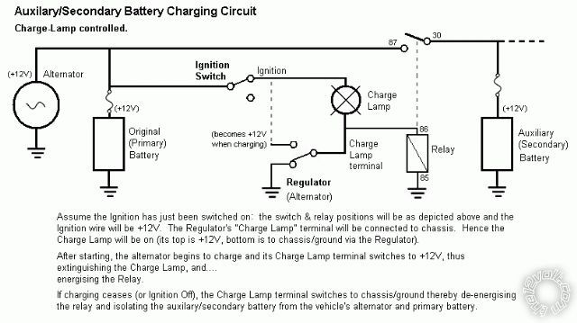
I like my 2-battery system as shown below. It's equivalent to common charge (voltage) sensing solenoids but uses the sensor that most vehicles have - namely the charge lamp.
It has worked well on Hitachi, Nippon Denso & Bosch alternators (with integral regulators) with 60 Ohm relays.
Some vehicles already have an equivalent relay for electric fuel pumps or similar accessory control - in that case you have that relay power your "aux battery" relay. Note though that some fuel-pump etc systems also get power during cranking (in which case the aux relay could be connected with its #86 to the existing relay output, and its ground #85 to the starter-solenoid circuit so it disconnects the aux battery during cranking).
Posted By: coolen
Date Posted: March 11, 2010 at 12:15 PM
That's an interesting set up. So if I understand right, the charge light is the "sense" sensor?
The vehicle I'm trying to have a system set up in is a 95 nissan pickup. Now I'm not 100% sure, but I didn't think that truck had a "sense" wire.
My idea with the solenoid would not work? I assumed that once it was shut off, it would cut the 2 batteries in two, and then the main battery would then receive a full charge.
With your above setup I could step down in wire size, as I have 4ga from my isolator to my aux batt.
Thanks
Posted By: oldspark
Date Posted: March 11, 2010 at 5:09 PM
Solenoid, relay - same thing. (Ambiguities - a solenoid is a coil as in the actuating coil of a relay. But a BIG relay is often called a solenoid.)
I bet your Nissan has a charge lamp wire - aka "D+" or "L" from the alternator. Or don't you have a charge lamp?
In single-wire alternators (ie, heavy B or B+ cable to battery +12V that all alternators have, plus a single other wire), the charge-Lamp "L" is called D+.
In 2- & 3-wire alternators, it is called L.
That goes to the dash's charge lamp as shown in the diagram.
It might instead go to a relay that controls charge and other lamps, but not on older vehicles.
That L/D+ circuit may also be diode-connected to other lamps that are tested upon IGN-on (eg, brake warning light). On older cars, these tested lamps also comes on whenever the alternators stops charging (and the ignition is on - eg, charge failure or engine stall).
The above diagram depicts a typical charge-sense relay (solenoid) system except that the after-market "smart" relays/solenoids use a voltage sensor to control the relay (#86) - eg, relay on if the main battery/alternator exceeds (say) 13.5 Volts (and off if below 13.0, and maybe if above 14.5 etc).
I had a system like that - a sensor with settable voltage and hysteresis delays - that would control the relay (in its case, a latching 80A relay).
But when it failed, I hit on the above idea.... (Alternators don't need water proofing against high-pressure engine cleaners.)
It's not quite the same as the voltage sensing method.
Instead, it connects the 2nd battery whilst its alternator thinks that it is charging.... ie, its charge lamp is off.
It is the same system that is used for many electric fuel pump relays where the fuel pump "shall be off if the engine is NOT running".
[ FYI: Hence if you have that fuel pump, consider connecting your relay's #86 to the fuel-pump relay's output so as to not add extra load to the (alternator) voltage-regulators L/D+ output - but other considerations include if the fuel pump is on during cranking or is ECU controlled (in which case it is better to have the new aux-battery relay supply the L/D+ signal to vehicle - ie, intercept the L/D+ with your #86 and relay, and feed its output (#87) to the battery and the original L/D+ wire; with a reverse-biased spike-protection diode across the original L/D+ wire). ]
It's a bit like saying that instead of the aftermarket voltage sensors turning on their relays when they think the car is charging, the alternator turns on the relay when it thinks it's charging.
Nice, simple, and it merely costs a relay - which you should have anyhow (unless you intend to parallel batteries full-time - but even someone that purports to be Jim McIlvaine, eCare Manager, OPTIMA Batteries, Inc. hasn't come back to me with evidence to support his statment that it is okay to do so on matched Optimas - I recommend avoiding it....).
Plus the all-important fuses at each end (which you MUST have anyhow!) - though I use circuit breakers (until I have some sort of blown-fuse alarm system!).
It's only if you have a huge solenoid that you might need a extra relay. (Yes: pun - or ambiguity - intended...)
IE - if a big relay (or solenoid) has a big-current solenoid (actuating coil) that might damage the regulator's charge-lamp circuit, then use a smaller relay to turn on the big relay.
I know that most alternators (Bosch, N-Denso, Hitachi (= Mitsubishi, Nissan etc)) can handle 60-Ohm solenoids - ie, about 200mA.
They can certainly sink (ground) higher currents (1 Amp and higher), but supplying +12V current may be limited to less.....
And a caution - jusy about every alternator (regulator) with a charge-lamp circuit needs the charge lamp (or other lamp or resistance) to reliably initiate charging.
Whether they continue charging if that +12V "trickle" or "tickle" current source (via the charge lamp or other resistance) is removed depends on the alternator/regulator.
And many alternators may initiate charging without a charge lamp, but that's not guaranteed (residual or remnant rotor magnetism refers).
And some systems (like the Bosch 2-wire S & L alternators) must have an L connected else their regulator will not function.
(I mention the this as a general caution, and also because I have seen so much incorrect information on the web etc.)
BTW - your "I assumed that once it was shut off, it would cut the 2 batteries in two, and then the main battery would then receive a full charge is half correct....
When off, the batteries are isolated.
But your main battery will NOT receive full charge because the system isn't charging.
Posted By: coolen
Date Posted: March 18, 2010 at 8:11 AM
BTW - your "I assumed that once it was shut off, it would cut the 2 batteries in two, and then the main battery would then receive a full charge is half correct....
When off, the batteries are isolated.
But your main battery will NOT receive full charge because the system isn't charging. What if while the truck was running and the solenoid off? I like the above idea and think i'm going to venture down that road. i have an optima red top as my starting battery, and a 12v gel cell type battery that was originally used to power cell tower sites when the power went out. i was lucky enough to get one of these batteries. i just need to effectively charge both. i was just going to put a solenoid inline between the aux battery and the isolator thinking once it was isolated, my starting battery would take a complete charge. and after a few hours of run time on my aux batt- i'd just turn the solenoid on to charge. thanks again
Posted By: coolen
Date Posted: March 18, 2010 at 8:15 AM
and yes my pickup does have a charge lamp. i learned that the last time i experienced an alt failure. Thanks
Posted By: oldspark
Date Posted: March 18, 2010 at 1:36 PM
Cool - you can use that system.
To recap - the other battery(s) are ONLY connected to the main battery when the system is charging. Hence you do not parallel idle batteries.
Nor do you flatten both batteries due to a heavy discharge from one battery (unless whilst charging and the load exceeds the alternator output and hence discharges BOTH batteries - that is one advantage of the voltage sensing system which would isolate the 2nd battery - but then reconnect, disconnect etc; the better solution is the charge-lamp system with a voltmeter and vigilance or alarms).
If the relay is off whilst the system is charging, it functions like the normal system with no extra battery(s).
By using a master-slave setup - where the charge lamp controls a 15A or 30A MASTER relay which the controls bigger slave relay(s) that would otherwise overload the charge lamp circuit, any number of slave relays can be used to isolate any number of batteries.
By inserting a diode between the charge lamp circuit and the (master) relay (#86), other +12V sources can be used to manually control the relay - eg, also through diodes, a momentary push button to join the batteries during cranking, or a switch to parallel batteries after a charging failure so you get maximum range etc.
(Usually those circuits are used when the charge lamp controls a fuel pump so you can manually prime, or manually bypass in case of charger failure. The aux-battery circuit is identical in all ways to the fuel pump circuit.
And note the reservations about solenoid resistance.
I have had no problems with 60-Ohm (200mA) relays (solenoids/coils) and I know some systems have had 2 such relays connected.
Alternators should be designed to drive a "reasonable" relay (say 200mA) since many vehicles use the charge-lamp circuit to energise relays (whether fuel pump control, electric chokes, fuel-cut solenoids, etc).
That means the alternator's regulator D+ or L (charge lamp circuit) has to be able to supply at least 200mA when the system is charging.
Most charge lamp circuits can sink probably 1 Amp or more when NOT charging - ie, they must be able to ground a 3W charge lamp (3W/12V = 250mA), but also any other lamps that may come on - eg, "tested lamps" like brake-fault, low fuel (EFI), oil filter (diesel) etc in typical vehicles from the 1970s to 1990s.
It's not uncommon to have 2 or 3 tested lamps, so that the charge lamp plus 2 or 3 others - eg, say 4x2W or 4x3W lamps = 12W = 1A @ 12V.
If the alternator uses a relay to flip the charge lamp from ground to +12V, then it should be symmetrical - ie, source and sink the same current - probably a few Amps.
But some alternators use solid-state switching so their current capability may be limited and not symmetrical.
I was looking at some 200A, 400A and 600A relays (solenoids) today. They had coil resistances of about 28 Ohms - hence about 0.5 Amps.
I reckon most alternators should be able to drive that, but if not, I'd use an intermediate transistor or FET, else a "normal" relay - e a typical 15A or 30A automotive relay (which are usually at least 60 Ohms, hence under 200mA).
Posted By: oldspark
Date Posted: March 18, 2010 at 2:11 PM
Just in case...
coolen wrote:
i was just going to put a solenoid inline between the aux battery and the isolator
Do you mean the charge-lamp relay between the battery and another isolator??
(If so, no! The charge-lamp relay is the isolator.)
And I wouldn't worry about leaving the solenoid/relay off until after some drive time.... (Unless you are going above 15V to force especially high current into the Optima...)
The fastest way to charge the batteries (as a whole) is to have them both connected.
Only if the alternator can't charge both would I consider isolation during charging, and only then if the lower charge is detrimental (which it shouldn't be - in fact fast(er) charging should be friendlier).
But you'll probably find that at normal RPM, the alternator is at less than full (current) output with just one battery, so why not use its extra capacity to charge the other battery(s)?
(There are arguments.... but I think I'll research certain batteries.... I know some arguments are based on certain industry information, but I have a feeling "that crap" is about to be blown out of the water....)
|