radiator fan wiring
Printed From: the12volt.com
Forum Name: General Discussion
Forum Discription: General Mobile Electronics Questions and Answers
URL: https://www.the12volt.com/installbay/forum_posts.asp?tid=122385
Printed Date: May 13, 2026 at 7:25 AM
Topic: radiator fan wiring
Posted By: mad-dax
Subject: radiator fan wiring
Date Posted: June 22, 2010 at 1:21 PM
I know about electronics but i am puzzled..My radiator fan has two wires. The blue is going straight to the 12v batt. fused, the black is going to a switch I have on the armrest and then to ground so I can turn it on and off at will. Why would power, 12v, be coming back out of the fan on the black wire that is supposed to go to ground. See what I mean now? In other words the if the fan is out of the car..it has two wires blue and black. I hook the blue wire up the the battery charger pos. Then I take my volt meter and test the ground wire which is hook up to nothing...and it has 12v on it. This is supposed to be going to ground...I don't think that the ground wire should have power coming out of it from the fan. This makes no sense...it shorts when i put it to the neg. I have tried another exact fan from another car and it seems to do this too. Are both shorting inside the fan sending 12v back up through the ground? or is this normal. I think another fan I tested that was a different brand did not do this.
Replies:
Posted By: i am an idiot
Date Posted: June 22, 2010 at 1:48 PM
Voltage is traveling through the motor, without ground connected, this is normal.
Posted By: 91stt
Date Posted: June 22, 2010 at 2:00 PM
a motor is basically coiled wire, when a circuit is not completed across the windings, it act the same as straight wire. When it is part of a circuit the inductance in the winding will prevent a short.
-------------
This information is provided only as a reference.
All circuits should be verified with a digital multi-meter prior to making any connections.
Posted By: mad-dax
Date Posted: June 22, 2010 at 4:40 PM
Oh so this is why it sparks then when connected to ground....so the 12v stops coming out of it when the ground is finally hooked up.
Posted By: 91stt
Date Posted: June 22, 2010 at 5:07 PM
Sort of
When the circuit is open, not complete, the motor does not act like a load.
There is negligible voltage drop because the windings have low resistance.
When the motor is part of a completed circuit, you will be able to measure the potential difference between the power side and the ground side.
You get a spark when you connect the ground because for a motor or any inductive load, for that matter, in the initial milliseconds the circuit is completed the motor windings act like a short until inductance kicks in.
The load of a motor is a result of inductance.
This is pretty simplified but I think gets the point across.
-------------
This information is provided only as a reference.
All circuits should be verified with a digital multi-meter prior to making any connections.
Posted By: oldspark
Date Posted: June 22, 2010 at 5:46 PM
Keep in mind that it doesn't matter WHERE the switch is.
The power/electricity must "loop" to flow...
EG we think of it "conventionally" as current flowing out the +ve terminal thru wires thru the load & back thru wires in to the -ve terminal (thru the battery out the +ve terminal thru wires...).
Break that loop ANYWHERE and the electricity flow stops, hence no power (flow) and no fan.....
FYI: (stop here - do not read below....)
What you describe is an earth or ground switched system, aka cold-switched (as opposed to HOT = +12V above ground etc).
Its advantage: no "hot" wire to switch and back so that if the wire is damaged, there is no hot exposure (ie could short to gnd).
Also that you can use less wire the GND connection can be to the chassis etc.
Also for "mixed" loads or supplies - you could use the same switch to turn on a 12V & 24V or 6V fan (assuming the different voltage supplies share the same GND). (Not that that's a practical example, but controlling things with different power sources is - see f.ex "Open Collector" switching as used in computers & logic/digital circuits - it's the same as many vehicle ignition coils, horns etc; sometimes lights or relays....)
Posted By: i am an idiot
Date Posted: June 22, 2010 at 5:47 PM
How much current is the switch rated for? It is normal for a medium/large cooling fan to pull 40 to 50 amps of current at startup. You would really be better off using a relay.
Posted By: oldspark
Date Posted: June 22, 2010 at 6:16 PM
Good point!
I had a 16A rated switch for an 80W fan (~7A) until the switch melted.
I've always used a relay since then and never had any problem. (Inductive loads - always a hot topic.)
Posted By: mad-dax
Date Posted: June 22, 2010 at 7:29 PM
Good news...I have two relays one for each fan (two fans). The switch is still on the arm rest, 30A and the switch triggers grounds on the relays. The fans are 80w each. I have the pos+ to 14 guage hot at all times, fused, each of those wires less than 3 ft. The other fan whiched I checked like 3 times does not flow pos 12v through the ground wire...but it works fine...that is why thought there was something wrong with the one I was asking about.....they are two different fans but off the same car. One is a radiator fan the other is a condenser fan but I rewired them like ubove and they cool the new radiator i got.
Thanks guys
Posted By: i am an idiot
Date Posted: June 22, 2010 at 8:09 PM
If both fans turning on at the same time are dimming your headlights too much, it is very easy to delay one of the fans for a second or 2.
Posted By: mad-dax
Date Posted: June 22, 2010 at 8:16 PM
i am an idiot wrote:
If both fans turning on at the same time are dimming your headlights too much, it is very easy to delay one of the fans for a second or 2.
You musta saw me turn them on last night while driving...uh yeah it makes my volt gauge drop from 13 to 11. My blinkers do that too though but even more on the gauge. Please..what is the fix?
Posted By: i am an idiot
Date Posted: June 22, 2010 at 10:33 PM
Give me a minute.
Posted By: i am an idiot
Date Posted: June 22, 2010 at 11:06 PM
I could not find the diagram that I thought I posted. Since I will have to draw one, what are you switching to energize the relay? Your switch is connected to either 12 volts or to ground. Which is it? I will draw the diagram accordingly.
Posted By: mad-dax
Date Posted: June 23, 2010 at 11:30 AM
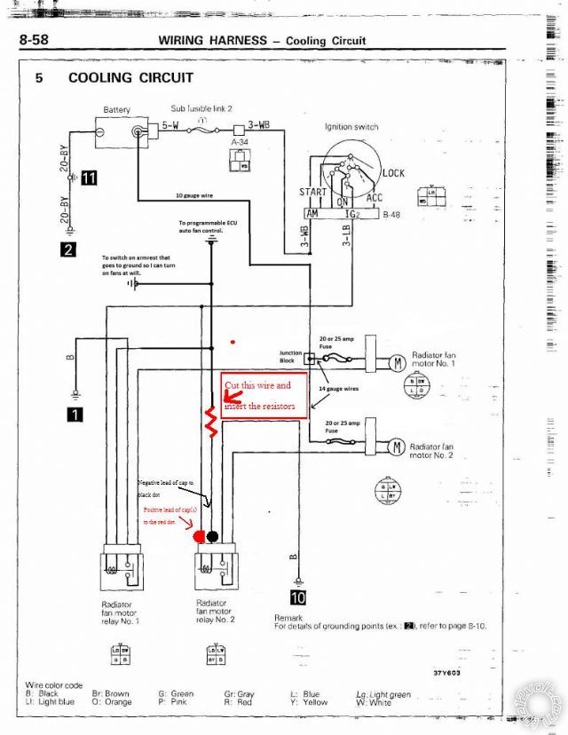
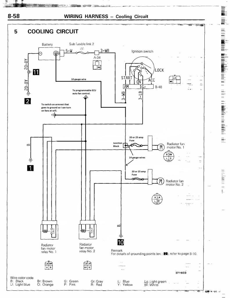
I redrew a factory relay diagram to show what I did. I am using the stock relays, I just wired them like the pic and took out the thermosensorswhich I erased out of the picture too.
https://i156.photobucket.com/albums/t18/gr8white1/2JZ%20Project/CoolingRelays2JZ.jpg
Posted By: i am an idiot
Date Posted: June 24, 2010 at 8:59 PM
Hey I forgot about it. I will draw something up tonight.
Posted By: mad-dax
Date Posted: June 24, 2010 at 9:50 PM
That's why your an idiot...j/k
Posted By: mad-dax
Date Posted: June 30, 2010 at 10:23 PM
hey i was only kidding please tell me how to delay those relays from each other...Also is this how tail lights can be delay each bulb to give the pointing arrow effect like the mustangs I have seen?
Posted By: i am an idiot
Date Posted: July 01, 2010 at 4:19 AM
I forgot again, let me try it without a picture, Radio Shack sells a 4700 microfarad capacitor rated at 35 volts. It sells for 5.49, it may take 2 of them. They also sell some 1/2 watt resistors, get a pack of 470 ohm, there are 5 per pack. Parallel the cap across the coil of the relay. The cap is polarized. Ground and positive must be placed on the corresponding connection of the relay's coil. Parallel 4 of the resistors and cut the wire that grounds the second relay, the resistors are to be placed in series with this wire. The way this works is the relay will not energize until the capacitor charges, the resistor limits the current that gets to the cap and relay coil. More capacitance or more resistance = longer delay.
You may want to mach it up on the bench to test it. I am thinking that you should be able to get a full second delay by using both capacitors, and 3 4 or all 5 of the resistors.
Posted By: mad-dax
Date Posted: July 01, 2010 at 9:14 AM
Uhh..yeah I need a picture.....I don't think I know what some of your terms of words mean.
Posted By: i am an idiot
Date Posted: July 01, 2010 at 2:50 PM
Posted By: mad-dax
Date Posted: July 01, 2010 at 11:40 PM
Man that picture explained it to me in like 5 seconds....why does my brain work like that vs. a word problem.
Posted By: oldspark
Date Posted: July 02, 2010 at 3:12 AM
3 main methods of perception: written/reading, graphical/pictorial, and aural/spoken.
Most favour one over the others.
Some are hopeless at one.
Or two.
And I know many that are hopeless with all 3! (I think they use touch. They are like keyboards - you have to punch the information in. Several times. And I recommend with great force!)
Speaking of the latter, a former boss reckoned I was strong at aural whereas she "suffered" because she was pictorial.
I explained to the fool that I too was visual/pictorial, but as I listened to or read explanations, I'd picture them in my mind.
Alas I think the only sense she had working was her smell.
(Maybe it was her mouse. ....That's a Scandinavian keyboard joke.)
If pictures & diagrams were not so good, there would be a saying "a few words are worth 1,0000 pictures".
Don't worry - your senses are in good company.
Posted By: mad-dax
Date Posted: August 19, 2010 at 1:21 PM
Ok I finally got around to making this on a bench....it doesn't work....What happens is if the relay is plugged into the loop it drains the 12v and clicks "off" and then the volts remain at ~1v. If I unplug the relay the cap charges to 12v in about 4 seconds. using 1 470 ohm resistor. I guess the relay drains the cap and then the volts is limited to what the resistor allows across it like 1v? the cap never can charge up again if the realy is plugged in.
I need to know how to get the slow ramp up to 12v then stay steady even with the relay plugged in. Maybe the relay coil resistance has something to do with? the coil seems to be 101.7 ohms. I am lost.
Posted By: i am an idiot
Date Posted: August 19, 2010 at 1:36 PM
Try to parallel another or 2 more 470 ohm resistors.
I will look at it tonight to see what I can figure out.
Posted By: oldspark
Date Posted: August 19, 2010 at 5:18 PM
The resistor drops the voltage to the coil - on 12V it will get ~2V (if in series with 470R) if it's connected as per that diagram.
The resistor should be feeding the capacitor - not in the coil circuit....
PS (2 hours later) - that resistor still forms a voltage divider with the relay coil.
The resistor must be reasonably smaller than the coil resistance. (For a high current fan, I wouldn't go above 20% of the coil resistance - ie, ~22R.) But that's why I prefer an RC feeding a transistor of FET etc.
|