pulse width modulation for a solenoid.
Printed From: the12volt.com
Forum Name: General Discussion
Forum Discription: General Mobile Electronics Questions and Answers
URL: https://www.the12volt.com/installbay/forum_posts.asp?tid=122940
Printed Date: May 13, 2026 at 8:11 AM
Topic: pulse width modulation for a solenoid.
Posted By: theboxmodder
Subject: pulse width modulation for a solenoid.
Date Posted: August 02, 2010 at 1:31 AM
1991 Eagle Talon TSI AWD Turbo Automatic
OK, I'm trying to control the pressure solenoid in my automatic transmission. It is controlled by a solenoid the is either open or closed. From what I read it is Open = full pressure and Closed = no pressure. Of course no pressure is bad. Very bad. so I'm looking at maybe 40-100% pressure to be my area of operation. Right now I am manually controlling the transmission using switches. The switches control two solenoids thus controlling the current gear 1-4. When I switch gears I have full pressure so it basically slams into gear. I want to be able to control pressure and make switching softer. I am assuming that the signal is 100hz.
Let me know if you have any information.
Replies:
Posted By: oldspark
Date Posted: August 02, 2010 at 4:12 AM
A 100Hz solenoid?
It sounds like you need a variable pressure device.
How is it supposed to be done, or how are others doing it?
Posted By: theboxmodder
Date Posted: August 02, 2010 at 5:10 AM
Well, no one is doing it. And the one person I know of that did do it is gone. The solenoid is inside the transmission and body grounded. A 555 circuit is too low amp to use too. I'm looking at around 10a max at 12v.
Posted By: oldspark
Date Posted: August 02, 2010 at 5:29 AM
So get a MOSFET (20A or more) and drive that from 555 pin #3 through a resistor (82 Ohms or more).
Is there are reason others are not doing it?
And what frequency was that person doing it at (and did his solenoid survive)?
Posted By: KPierson
Date Posted: August 02, 2010 at 6:24 AM
Ideally your PWM output would be based off of some sort of input (RPM, TPS, MAF, etc). Are you looking to have an intelligent system or just an open loop output? If you don't want the PWM to ever change (or require a manual change) the 555 driving a mosfet is ideal. If you want something a little more sophisticated then you'll have to go more advanced then the 555.
-------------
Kevin Pierson
Posted By: oldspark
Date Posted: August 02, 2010 at 6:50 AM
I assumed a voltage or pot input since its manual (at the moment) - eg
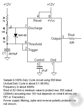 .
(Modify for a minimum duty cycle - that one's optimised for a 99.8% variation (at ~400Hz). Or modify for voltage input etc.)
Of course, if a uPC is being used for the decision control....
Posted By: awdeclipse
Date Posted: August 02, 2010 at 6:59 AM
Have you been to the DSM Forums yet to try and dig up some info on this mod?
Posted By: theboxmodder
Date Posted: August 02, 2010 at 10:08 AM
Yeah I've been on DSM everything looking. Only "Blue Wire" mods. No one has done this except TCUGO. And Hugo stopped making them a long time ago. I'd imagine he wouldn't tell me how he did it either. Trade secret? Either way. I need to figure out the pulse width. But I am a complete newb when it comes to that. I can understand simple 555 circuits. Like 2 resistors and a cap. But I have no clue as to how to incorporate anything else. :( I have not indulged into electronics enough to understand a lot of it. I've replaced components and troubleshot some devices. But never got into designing complex circuits. But. After some research I want to be able to automatically control the PWM via TPS and the pulse generators on the transmission. That way I can get clean shifts no matter the RPM/Gear combo. That's a whole new level ATM.
The solenoid is designed for this type of operation. The transmission uses a PWM to regulate fluid line pressure stock. The issue is finding out the pulse width that the solenoid uses.
Posted By: oldspark
Date Posted: August 02, 2010 at 12:18 PM
It's not so much pulse width that matters, but its frequency. EG - that 555 circuit runs at ~400Hz and varies its pulse width from 0.1% to 99.9% (2.5uSecs to 2.4975mS in a period of 2.5mS).
You should only need 2 parameters - the max or ideal frequency for the solenoid(s), and the minimum pulse-period (if it matters).
If the solenoids cannot handle 100% duty or continuous on, then you also need the max duty cycle or max on time (over whatever cycle time - eg 5 seconds per minute etc).
As to implementation, initial testing could be via pot (variable resistor to change duty cycle of the 555).
Then when the control method is decided, modify appropriately. EG - if TPS or MAF voltage proportional, use the voltage instead of the 555 pot (with suitable conversion or 555 supply voltage if required).
RPM could feed an LM2917 freq2voltage converter to the 555.
If signal processing is required (outputs are not proportional to PWM), then I'd suggest something programmable (uPC else PIC) unless it's a simple relationship.
If sensors (TPS, MAF) are digitally coded, the ditto for uPC, PIC etc. (Simple pulse rate like tacho/RPM is as above.)
And if a combination of signals (as for ignition timing or EFI etc), then uPC, uPC, uPC or a PIC etc.
Posted By: KPierson
Date Posted: August 02, 2010 at 2:46 PM
Pulse width can be measured with a $25 volt meter from Sears (just make sure it measures frequency. Some of them might even read duty cycle which would tell you stock parameters at idle and for "light shifts".
You could set up a simple table that monitors TPS voltage and then looks up current speed (ie pulses from tranny). You could then have a programmable duty cycle for every possible combination with decent resolution. Unfortunately, it would all have to be custom engineered from the beginning and would be a pretty large project for someone with little electronics experiance. ------------- Kevin Pierson
Posted By: oldspark
Date Posted: August 02, 2010 at 8:16 PM
The programmable part can be looked after by boards like the FB (Fusion Brain; ~$70; uses a PIC/PICAXE) though I prefer uPC boards like the Arduino - eg the Duemilanove with its ATmega328 uPC for ~$40.
That latter has USB interface which can power it (I think the FB also) and being a uPC, it isn't as restricted as a PIC.
There is a plethora of free applications & software for the Arduinos (its a public-domain based project).
But both require programming nouse else the ability to modify suitable programs. Many reckon PICs are far simpler than uPCs, but I found the PICs too complex else limited & decided to re-learn the ATmega commands intead (I have previous programming experience albeit in Assembler. Using higher languages (like C++ etc) is far more common and should be simpler (as well as transportable between devices assuming feature compatibility, redefined addresses/register location etc, and suitable compilers. (Sorry, that's a bit too tech but its an extension of programming which is not an uncommon skill these days.)
And both require the added interfacing, though that should be minimal. Both have onboad ADCs (analog to digital converters) so inputs should be simple (resistive dividers etc) and outputs into MOSFETs etc. Both feature PWM outputs.
But having decided on a platform (FB or Arduino) I'd expect that you'd fine coding (programs) to do what you want - eg, read a value; use a look-up table to modify it; send that to the PWM and output it to the solenoid driver.
But if you find you have simple linear transformations (duty-cycle is proportional to a straight-line input), then simpler 555 circuits etc will do.
No more buts.
|