1996 Dodge Dakota Fuel Pump Power Issue
Printed From: the12volt.comForum Name: General Discussion
Forum Discription: General Mobile Electronics Questions and Answers
URL: https://www.the12volt.com/installbay/forum_posts.asp?tid=123702
Printed Date: May 13, 2026 at 3:34 AM
Topic: 1996 Dodge Dakota Fuel Pump Power Issue
Posted By: issakar
Subject: 1996 Dodge Dakota Fuel Pump Power Issue
Date Posted: September 28, 2010 at 5:49 PM
Hello there forum!
This is my first post on here and I'm glad I stumbled across this site! The problem I am posting may be a little unique for this site but I feel that given the great electrical oriented minds on here i may be able to get some help :-D
I have a 1996 Dodge Dakota Extended cab truck that I have been having problems getting to start. It has been narrowed down to a fuel delivery issue related to the fuel pump not powering on. The pump was replaced about 2 months before this current issue. I have tested power at the fuel pump connector while supplying a direct battery connection and it read at 10v. I did this with the connector removed from the pump. I originally thought the wiring harness had a break in it but that doesn't appear to be the case now.
I am looking for some advice on what diagnostic tests to try. Also any tips/tricks etc. I need to get this truck running because its been sitting for a while and the city gets kranky about that kinda thing, lol.
Thanks foruM!
Replies:
Posted By: oldspark
Date Posted: September 28, 2010 at 9:51 PM
If you connected a 12V battery across it, it should have 12V across it.
Why is it only 10V?
Bad GND?
Or current so high it causes a voltage drop in the supply path?
Reply ends.
The rest is FYI in lieu of wiring diagrams and further info:
Fuel pumps should be powered via a relay which is ECU controlled else some other "yes - the engine is running" mechanism - eg, alternator is charging; airflap is open; splugs or IgCoil are firing; crank or ring gear is rotating. (But NEVER oil pressure!)
There should also be a priming function - eg - on for a few seconds when IGN is turned on (especially for EFI), or on when cranking. This can be done by the ECU else SPDT relays or dual-coil SPST relays or diode-OR connected signals; etc.
But testing the fuel pump as you have with 12V directly accros it is a good first check. WARNING - that assumes it is a 12V pump (not 8V or 6V etc) and is disconnected as you indicated.
Some pumps use a series resistor to drop voltage for various reasons. AFAIK however, all 12V vehicles use 12V pumps and only use a dropping resistor during low demand periods. (And I think that is rarely done.)
Posted By: issakar
Date Posted: September 30, 2010 at 8:05 AM
I appreciate all the information you supplied! I feel this will help me out. I have a few things to try today and I will post back with the results from there.
Thanks!
Thanks!
Posted By: issakar
Date Posted: September 30, 2010 at 3:53 PM
so the pump is only getting about 7-10v at the connector. I checked the fuel pump relay, and the relay output (which feeds the pump circuit) is only giving me 7-10v when i pipe a direct battery connection to it. I have 12v at the relay power side, only about 7 on the output side that feeds the pump no matter how i attach power to it. This seems weird
Posted By: oldspark
Date Posted: September 30, 2010 at 5:18 PM
I agree - it's weird....
If it's a normal relay, then Vin should be Vout except for insignificant contact voltage drop. (EG - if contact resistance is 10mR (milli-Ohm), then if 10A, from V=IR => V(drop) = 10A x 0.01R = 0.1V. But you have a 2V - 5V drop! (0.2R - 0.5R if a 10A pump; higher resistance if lower current.)
But if it's a special relay with inbuilt resistor or something, anything is possible. And there is a relay (for a 1997? Dakota) that looks long - a bit like some horn relays but with several pins in an attached plastic surround - I'm wondering if that includes a resistor?
I reckon replace the relay. There are several reports of them going faulty.
And since I can't find anything that suggests voltage dropping for the pump, I'm tempted to suggest try 12V direct to the pump (not via the relay).
Maybe powering a 12V bulb via the relay (instead of the pump) might show flickering if contact resistance varies. (Could try both small 3W-10W bulbs and (non-HID!) headlamps.)
Else remove the relay and test its ON contact resistance....
Certainly if it is an ordinary relay (the mini Bosch/Hella types as shown here on the12volt), I'd swap relays, or maybe jumper the #30 and #87 wires/connectors together on the wiring harness or relay socket. (That's to connect power. Paper clips can work well - until they short to GND/chassis!)
The above is a bit risky. I have no idea how your vehicles are wired (I'm in Australia mate!), though I feel fairly confident... (As I said - where do you find 6V or 8V fuel pumps??)
And FYI - Yes - I searched for Dakota stuff.
Of note from Wiki.Answers was:
How do you check the fuel pump on a Dodge Dakota?
- There is a relay that runs the fuel pump, but before you start probing around in there UNPLUG the PCM, (engine Computer), then loosen a fuel line and apply power to the relay and see if you get fuel. >>>> CAUTION <<<<<< I can't stress enough UNPLUG the MAIN ENGINE computer before you do this, If you don't It will most likely blow the computer.
And from allexperts (Aug 2006):
My 1996 Dakota was stalling when I come to a stop and we put everything in the way of tuneup and sensors on it then a guy at the car wash said his Dakota did the same thing and it was the fuel pump relay. I changed it and problem solved - cost $6.50.
Posted By: issakar
Date Posted: September 30, 2010 at 5:34 PM
Hey old spark, thanks for the reply again. This is actually happening with the relay removed and the multimeter sitting in between the pins. That is why it seems so strange. the factory service manual lists the pins on the relay as follows
5A: Iginition Switch Output
5B: Fused B(+)
5C: Fuel Pump Relay Control
5D: Fuel Pump Relay Output
So my understanding of this is as follows:
5A and 5C power an electromagnet inside the relay itself. this magnet then pulls 5B and 5D together to close the fuel pump circuit causing power to run to the pump.
It is the connection of 5B and 5D that I have the discrepancy. 5B is giving me full battery power of 12.3v output. As soon as that is connected to 5D via a multimeter (or paperclip, jumper wire, etc) is when i see the voltage drop. if i hook the battery direct to 5D, same exact scenario, with multimeter, jumper wire, etc. It seems like major resistance somewhere along the A141 circuit (what 5D feeds) perhaps? I really am kinda stumped at this point. I'm pretty new when it comes to electricity and such so I am still learning. I feel I have a fairly decent (yet basic) understanding of how this system is working though.
Thanks for the extra info you gave me, I appreciate it! I feel like if i could run a direct 12v connection to the pump I would see an improvement in my situation; however I don't have the ability to do that right now.
Thanks again for hangin' in there with me!
Posted By: oldspark
Date Posted: September 30, 2010 at 11:42 PM
Okay - that's a bit vague.
But before that, confirming the good stuff.
(AFAIK....)
Yes - that "control" is typical....
So 5A is IGN-switched +12V to the coil (aka #86).
5C "Fuel Pump Relay Control" is thus a grounded signal from an ECU etc to energise the coil (#85) to turn the pump on & off. (IE - apart from an initial prime, it should be off unless the engine is cranking or running. It's the equivalent of an air-flap or "ignition-sparking" or alternator-charging signal etc.
... and...
5B is fused +12V (aka #30).
5D is switched power (+12V?) for the pump (#87).
What I don't get is that if a short (paper clip) connects 5B to 5D, then both MUST be at the same voltage - ie, 12.3V, or 7V etc.
If not, then (12.3-7=) ~5V must be dropping across the paper clip which means it might glow red hot for a while until it fuses... (LOL?? or Ouch!!)
So can you re-check or clarify that?
If "the clip" drops 5B & 5D to low volts, that means the resistance is "upstream" - ie, between battery-fuse-5B.
That can be bad connections (break and reconnect them) or bad fuses (rotate or swap fuses), else maybe a burnout wire or bad relay mount joint.
If the clip remains at (near) +12V, then the fuel pump should also be getting +12V. (Unless ditto - bad connections or wire).
With the relay in, if 5B is 12V and 5D is significantly lower (say > 0.2V lower), then the relay has resistance whether that be bad contacts or inbuilt dropping resistor.
Note that connecting a voltmeter between 5B & 5D won't tell you much - it should read either ~12.3V else 0V. If it does read 3-5V or 7-9V then you do have a weird fuel pump (like it's floating but with a zenor diode etc...!?... No way! (??).)
The above is fairly easy to understand with a pretty pic and understanding that a voltmeter passes/consumes negligible current (ie, 1uA versus >1A for fuel pumps; a voltmeter is a VERY high resistance).
Posted By: issakar
Date Posted: October 01, 2010 at 6:55 PM
Oldspark,
I really appreciate you working through this with me. I picked up a spool of wire today at work and plan to run a direct feed back to the fuel pump and see what it does. Probably wont have time until tomorrow or so to do this but i will keep you in the know on what happens. would it help at all if i posted a copy of the wiring diagram n such that I have been using on this? I have a copy saved on the web that i can link in.
thanks again!
Posted By: oldspark
Date Posted: October 01, 2010 at 7:14 PM
Yes! That wiring diagram might (should?) show any resistor or dual-mode switching.
That can change my ~90% confidence to 100%. (Well, 100% that no damage can be done, less whatever improbability factor applies LOL).
That can change my ~90% confidence to 100%. (Well, 100% that no damage can be done, less whatever improbability factor applies LOL).
Posted By: issakar
Date Posted: October 01, 2010 at 7:19 PM
stand by I will get that for you right now.
Posted By: issakar
Date Posted: October 01, 2010 at 7:23 PM
relay guide

wiring diagram

wiring diagram
Posted By: oldspark
Date Posted: October 03, 2010 at 12:43 PM
Sorry for the delay issakar.
First I had trouble saving the pics because they are PNG which only show on screen, not when viewed from the saved file. (Or is that just me; I've forgotten "copy-protection" stuff - but not print-screen as bitmaps and good old MS Draw.)
Then those rotten IEC contact symbols. But the "capacitor" and "variable capacitor" symbols on the FUEL PUMP RELAY merely mean a normal SPST contact/switch.
Conclusion(s):
You can use an SPST relay but it should have a Protection Diode. SPST relays with protection diodes are common. Else you could buy your own (eg) 1N4004 or 1N4007 diode (~20c each - I suggest a few spare; & they can be useful for other things...) and wire the diode into the base.
There are no resistors etc.
Wiring confirmation (for Bosch type relays; see diagram)...
5A to #86
5C to #85
5B to #30
5D to #87
No indication of current rating and 15A should suffice, but I suggest the (more?) common 30A type - ie a 12V/30A SPST relay.
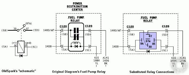
[ POST EDIT - I have updated with the above diagram. I hope it makes sense, and isn't wrong! ]
The rest hereunder is trivial...
"AUTOMATIC SHUT DOWN RELAY OUTPUT" (FUEL TANK MODULE C327) is a crappy name for "the Fuel Pump".
And "FUEL TANK MODULE"' is a crappy name for a "Fuel Tank".
The former is NOT an output and the latter is NOT a module (IMHO).
"From (or To) AUTOMATIC SHUT DOWN RELAY OUTPUT" and "FUEL TANK Assembly" may be acceptable. But I'd prefer "From FUEL PUMP RELAY" or better still, simply "Fuel Pump" and "Fuel Tank". It's a simple wiring diagram!
(Per chance, did Microsoft write their documentation?)
Personal Conclusion - I should just analyze on screen instead of thinking I always need to print diagrams and legends. Only one "block" in the relay guide was relevant (d'oh!) and the wiring diagram was easy (d'oh #2!)
FYI - the circuit is "typical".
The fuel pump is powered from the (fused) battery (#30, 5B) thru the relay (#87, 5D).
It's a "hot" coil - ie, Ignition +12V to #86/5A - which is grounded (#85/5C) by the C19 FUEL PUMP RELAY CONTROL (POWERTRAIN CONTROL MODULE; C175) to turn the pump on. (Probably an "Open Collector" transistor; it "floats" when off and shorts (connects) to GND when on. That is typical for digital EMS/ECU etc outputs.)
First I had trouble saving the pics because they are PNG which only show on screen, not when viewed from the saved file. (Or is that just me; I've forgotten "copy-protection" stuff - but not print-screen as bitmaps and good old MS Draw.)
Then those rotten IEC contact symbols. But the "capacitor" and "variable capacitor" symbols on the FUEL PUMP RELAY merely mean a normal SPST contact/switch.
Conclusion(s):
You can use an SPST relay but it should have a Protection Diode. SPST relays with protection diodes are common. Else you could buy your own (eg) 1N4004 or 1N4007 diode (~20c each - I suggest a few spare; & they can be useful for other things...) and wire the diode into the base.
There are no resistors etc.
Wiring confirmation (for Bosch type relays; see diagram)...
5A to #86
5C to #85
5B to #30
5D to #87
No indication of current rating and 15A should suffice, but I suggest the (more?) common 30A type - ie a 12V/30A SPST relay.
[ POST EDIT - I have updated with the above diagram. I hope it makes sense, and isn't wrong! ]
The rest hereunder is trivial...
"AUTOMATIC SHUT DOWN RELAY OUTPUT" (FUEL TANK MODULE C327) is a crappy name for "the Fuel Pump".
And "FUEL TANK MODULE"' is a crappy name for a "Fuel Tank".
The former is NOT an output and the latter is NOT a module (IMHO).
"From (or To) AUTOMATIC SHUT DOWN RELAY OUTPUT" and "FUEL TANK Assembly" may be acceptable. But I'd prefer "From FUEL PUMP RELAY" or better still, simply "Fuel Pump" and "Fuel Tank". It's a simple wiring diagram!
(Per chance, did Microsoft write their documentation?)
Personal Conclusion - I should just analyze on screen instead of thinking I always need to print diagrams and legends. Only one "block" in the relay guide was relevant (d'oh!) and the wiring diagram was easy (d'oh #2!)
FYI - the circuit is "typical".
The fuel pump is powered from the (fused) battery (#30, 5B) thru the relay (#87, 5D).
It's a "hot" coil - ie, Ignition +12V to #86/5A - which is grounded (#85/5C) by the C19 FUEL PUMP RELAY CONTROL (POWERTRAIN CONTROL MODULE; C175) to turn the pump on. (Probably an "Open Collector" transistor; it "floats" when off and shorts (connects) to GND when on. That is typical for digital EMS/ECU etc outputs.)
Posted By: issakar
Date Posted: October 03, 2010 at 9:08 PM
Oldspark,
Thanks again for your continued support in resolving my issue. I really appreciate it and I am learning a lot! To think just a few weeks ago I couldn't even begin reading a wiring diagram, lol.
Do you think it is possible that all my issues could be related to a poor ground? I feel like yo may have mentioned this as a possibility previously but I don't recall right this second if that is so. I havn't tried my direct wire test yet due to a busy schedule and poor weather. I should have time this week, wednesday by the latest to really give it a shot and see what happens.
thanks again, I really appreciate you sticking with me through this!
Posted By: oldspark
Date Posted: October 03, 2010 at 11:05 PM
issakar wrote:
To think just a few weeks ago I couldn't even begin reading a wiring diagram...
THAT is what makes it so worthwhile and rewarding!
That is what the12volt strives to do. Solving the problem is one thing, but to make people realise what they are capable of... (I think that's called edukashun. Or is it self-actualisation & -realisation?)
But enough of my young(cough!) innocent (cough cough!) naive idealistic rambling!
A bad ground? Oh yes - definitely.
The common and evil ground-gremlin is probably the most basic yet confusing, damaging and subversive bug to exist in any electrical system!
[ Yes - it's true - Gremlins are really bugs! (Trust me...) ]
I did mention it - probably because I was lucky enough to remember the in-obvious obvious potential (pun intended - potential as in voltage).
And I suppose ~36 seconds would be enough for me to look back and check, but who has time for that?!
Check the voltages at FUEL TANK MODULE terminals 4 & 6 with POWER DISTRIBUTION CENTRE 5B shorted to 5C. They should near 0V. Perhaps 1V max (assuming the Fuel Pump is drawing its current).
BTW - I used the expert-TECH SPEAK you and now I are so familiar with. But let's keep the translation to ourselves!
The rest hereunder is optional reading...
A grounding in grounding:
Picture a ground as a resistor. It can be perfect - ie, zero resistance; bad can be from a fraction of an Ohm to many Ohms; or open-circuit (ie, infinite resistance/Ohms).
If open, the "thing" shouldn't (or won't) work, and all voltages upstream should be "high" and the same.
[ Open means zero current means zero voltage drop. Ohms Law: V=IR "The voltage across a device equals its resistance times the current going through it. ]
If perfect, we don't care. The "ground" voltage drop will be zero. (V=IR; if I = 10A, then V = 10 x 0 = 0V because "perfect" is zero Ohms/Resistance.)
But in practice, everything has resistance, but ground and power resistance should be small enough to minimise the voltage drops (which increase with increasing load/current).
Power grounds should me milli-Ohms if that.
EG - for 10A & 1mR, V=IR = 10A x 1mR - 10mV = 0.01V (or 10 x 0.001 = 0.01V).
NOTE - I am using "R" instead of the Ohm symbol Ω because I couldn't be bothered finding it... I mean, Ω can have problems in different fonts or applications, and since we don't understand foreign languages and R is on our keyboards anyway....
Where was I....?
Oh yeah, a 0.01V drop in a 12V system - bah! nothing, negligible!
But if the GND is 1/10th of an Ohm:
V = 10 x .1 = 1V. Hey - that's 1V in 12V - we are getting concerned.
Fit a 100A load or amp(lifier) to that... V = 100A x 0.1R = 10V. Now we do have a problem!
(In practice you won't get that current thru the circuit hence not that "ground drop" - the total circuit resistance limits the current. But that's for another time - let's keep it simple (coughs again!).
The point is bad grounds result in UNDER-current and voltage - the load probably won't work - ie amplifier, fuel pump etc.
[ In some situations, bad grounds can be damaging. Alternators can overcharge and cook batteries; electronics can fry due to inter-ground currents (across ground voltage drops) etc. ]
Hence the "Big 3" etc etc.
Trust me, I've tried to get rid of GNDs and electricity return paths but the things just refuse to work!
Selfish $#$@s!! - one "feed" isn't enough - they want TWO! Both the "feed" and the "return".
They must be of that Greenie recycler clan! (Good!!)
(The above was attempted humour.)
Rats! I've already explained the effect of a bad ground in the above example. Never a perfect ground eh? But good enough depends on the circuit....
Oh well, that gives me time & space to say that IMO, get a few "basics" and abilities simply accumulate...
The main basics include being able to understand wiring diagrams - including crappy ones!
[Break them down; isolate or do one section or circuit or wire at a time. A pencil or colored marker(s) can be godsends - especially on (multiple!) diagram copies!]
Then there is the basic understanding of electricity (that's where the water analogy is excellent!) and that usually involves an understanding of the simplicity of Ohms Law. (The pressure drop along a pipe is proportional to it's size and the amount of water going through it. IE - as size/diameter decreases its resistance increases, and more flow quantity means higher friction and turbulence - ie, higher resistance.)
[Water currents and electrical current - coincidence? I think not! (LOL)]
Most people "understand" Ohms Law - they just don't realise it.
Mind you, applying to a circuit can be tricky (I still get caught!), but you learn the tricks with experience. (Which in retrospect are so damned obvious, but....!!)
It is yet again breaking down in to basics - currents THROUGH a device and its "string" OR the voltage ACROSS various devices or strings (and their resistance) to work out total resistance or current. On part at a time...
Alas, ramble.
But I am curious if your last "could it be ground?" was a self realisation, or a subtle re-read (and thus flagged or realised).
If the former, I am impressed.
Though I'm still impressed with the latter - after all, you prompted me, I didn't remind you.
And better still, it wasn't a question AFTER buying a new relay, or pump, or battery, or vehicle!
But really, though I suspect it was self realisation, who cares?
I think your "... couldn't even begin reading a wiring diagram, lol." (ie, LOL) says it all!
Good luck - not that luck seems relevant in your case.
Posted By: issakar
Date Posted: October 06, 2010 at 3:58 PM
Oldspark!
sorry about the delay in response, funny how schedules fill up fast! I have had the chance to do some work today and found some pretty interesting results.
I made 2 jumper wires today from a spool of wire I got from a person i work with. I put alligator clips on the wires and hooked one to the fuel pump positive side. I then hooked the second one to the fuel pump ground and the other side of the wire to a section of the frame of the vehicle i had lightly sanded until it was nice and shiny, bare metal. As a precaution, I unplugged the PCM connectors to be sure I didn't fry anything. Once the pump was all hooked up, i attached the "positive" jumper wire to the B+ (12v) battery terminal (positive).
As soon as the clip came in contact with the B+ the pump hummed right up! I am really thinking this is a ground issue at this point.
btw [quote]But I am curious if your last "could it be ground?" was a self realisation, or a subtle re-read (and thus flagged or realised).
If the former, I am impressed. [/quote] in answer to that, it was more of a self realization. I was beginning to suspect a ground issue, but was not 100% sure. I asked that looking for a confirmation of if i was on the right track. I really think I am! What I am going to try next is putting everything back together, and leaving the pump connector off. Then I am going to connect a jumper wire to the feed side (pin 1 on the fuel pump connector C327) and to the pump pin 1. then i will keep the same ground to the frame setup I have right now. I will reassemble the PDC, reconnect the PCM, hook up the battery and crank her over. My hypothesis is that this truck will then start up!
I'll keep you informed on what happens as I get a chance to do it. I really appreciate all the advice and info, and always look forward to more!
Thanks again Oldspark!
Posted By: issakar
Date Posted: October 06, 2010 at 6:07 PM
Well Oldspark I got excited too soon. I have figured out that this most likely ISNT a ground issue and here is how.
I reconnected the existing wiring and such and ran a jumper from power pin to the pump and left the pump grounded out to the frame. NO PRIME. I checked voltage at that connector grounded to the frame and only 6-7v. So I am losing A LOT of voltage somewhere along the way. very intersting. I am thinking about just running new wiring for the pump. None the less I still want to try and find out whats going on! lol
I reconnected the existing wiring and such and ran a jumper from power pin to the pump and left the pump grounded out to the frame. NO PRIME. I checked voltage at that connector grounded to the frame and only 6-7v. So I am losing A LOT of voltage somewhere along the way. very intersting. I am thinking about just running new wiring for the pump. None the less I still want to try and find out whats going on! lol
Posted By: oldspark
Date Posted: October 06, 2010 at 6:19 PM
POST EDIT - I missed your last reply (probably because I was out rewarding the crows mid-reply), but it sounds like you "have it under control" - it's a seek&destroy issue; much as described below...
/end POST EDIT
[ A useless & qualified mechanic ~2 years ago claimed "fuel pump problem" on my mate's car despite my protestation, AND check methodology. Anyhow, 2 weeks later, one blown EMS-CPU later, my mate was the one that found the causal battery-fuselink problem. This ignoramus mechanic couldn't even jumper-lead a fuel pump! ]
As to "...it was more of a self realization. I was beginning to suspect a ground issue, but was not 100% sure" - good! That suggests "thinking" - a rare commodity these days. With that comes accelerated learning.
And sometimes caution is warranted.... "a little but of knowledge..." (can be a dangerous thing).
"I am really thinking this is a ground issue at this point"
Be careful - it can get confusing.
If the pump buzzes fine when jumpering the +12V feed ONLY, the GND is ok (probably).
If whatever you jump changes things, then that <whatever> is the problem (in "simple" systems).
But there is the possibility that the relay coil has a grounding or power problem.
VIZ - poor IGN +12V or poor control GND thru the Powertrain Control Module, hence coil/field not at full strength and the relay contacts are too light or chatter - hence contact failure.
But that's why a DMM to measure voltage drops across each section in operation is invaluable.
But certainly #4 & #6 at the fuel tank should be GND ie, 0V (or well under 1V? to chassis).
And C175 (#C19 Pwrtrn Ctrl Mod) should also be GND when the fuel pump should be on (eg, maybe initial IGN on for a few seconds and then when engine is cranking, and running; but NOT when is stalled).
As to delayed schedules - ha! Tues shifted to Fri; tyres yesterday not today (Thurs); funds that had not been transferred as at Tues had in fact been transferred Monday....
That's my snafu week! (But the local crows/ravens cleaned out a dirty roof gutter. Bonus FTW!)
/end POST EDIT
issakar wrote:Congratulations! I hereby declare you honorary mechanic!
As soon as the clip came in contact with the B+ the pump hummed right up!
[ A useless & qualified mechanic ~2 years ago claimed "fuel pump problem" on my mate's car despite my protestation, AND check methodology. Anyhow, 2 weeks later, one blown EMS-CPU later, my mate was the one that found the causal battery-fuselink problem. This ignoramus mechanic couldn't even jumper-lead a fuel pump! ]
As to "...it was more of a self realization. I was beginning to suspect a ground issue, but was not 100% sure" - good! That suggests "thinking" - a rare commodity these days. With that comes accelerated learning.
And sometimes caution is warranted.... "a little but of knowledge..." (can be a dangerous thing).
"I am really thinking this is a ground issue at this point"
Be careful - it can get confusing.
If the pump buzzes fine when jumpering the +12V feed ONLY, the GND is ok (probably).
If whatever you jump changes things, then that <whatever> is the problem (in "simple" systems).
But there is the possibility that the relay coil has a grounding or power problem.
VIZ - poor IGN +12V or poor control GND thru the Powertrain Control Module, hence coil/field not at full strength and the relay contacts are too light or chatter - hence contact failure.
But that's why a DMM to measure voltage drops across each section in operation is invaluable.
But certainly #4 & #6 at the fuel tank should be GND ie, 0V (or well under 1V? to chassis).
And C175 (#C19 Pwrtrn Ctrl Mod) should also be GND when the fuel pump should be on (eg, maybe initial IGN on for a few seconds and then when engine is cranking, and running; but NOT when is stalled).
As to delayed schedules - ha! Tues shifted to Fri; tyres yesterday not today (Thurs); funds that had not been transferred as at Tues had in fact been transferred Monday....
That's my snafu week! (But the local crows/ravens cleaned out a dirty roof gutter. Bonus FTW!)
Posted By: issakar
Date Posted: October 07, 2010 at 1:46 PM
Oldspark,
Check this out. So with my new jumper wires i made (handy things they are) i did a bit more testing. Here is what I found.
When i disconnect the lower wiring harness for the truck (works the fuel pump and lights and such. the c207 connector on the wiring diagram) and test the truck side of the connector i get 12v. this is good. it rules out interior wiring (behind the firewall), it rules out PDC issues, etc etc. everything on the top end looks good. Now, if i use a jumper wire and send a direct B+ connection down the line, and check at the fuel pump, guess what? thats right, low voltage- 8-9v to be exact.
So as another test, I took my jumper wires (these things are great!) and cut a slit on the insulation for the wire directly below the 207 connector. I did this to test of it was a connector issue or otherwise. same result, low voltage.
I left this setup intact and instead of hooking to B+, i connected the "positive" jumper wire lead to the pos meter lead. I then turned it over to continuity mode. I didn't get a reading on continuity. I thought that was strange so i switched it over to the ohms mode.
The only way I get a reading on the Ohms mode is if i set the meter to 2000k. Not a typo, two zero zero zero kay. lol. When i have it set to this setting, the reading is around 540, 539, etc.
I think I know what this means, but........
What does this mean?
Thanks!
Posted By: oldspark
Date Posted: October 07, 2010 at 6:37 PM
Er, I'm pre-coffee, and shouldn't be here...
Lots of things come to mind, but beware - breaking the ground C207 should "float" all the "other side" up to 12V since there is nothing to pull that down (to GND).
BUT that does not mean all is ok - it just means you have a 12V source at voltmeter currents - ie micro-Amps.
It will not detect if there is 1, 1k & maybe even 1M Ohm resistances in the line.
IE - start putting current thru that path, and the voltage may drop (burnt relay contacts; bad connections, etc).
The 7V readings... I did say I was pre-coffee eh?
Oh - I shouldn't be here - I'm off wood collecting....
(Never been so happy for physical work in my life!)
Later.....
(..." coming dear....")
PS - not using Resistance scale on a powered circuit? (That's a no - no.)
Posted By: issakar
Date Posted: October 07, 2010 at 7:01 PM
Have a good time, I'm off to make dinner and such myself, lol. Different time zones are great, arent they?
BTW, no, I did not use the meter on a powered circuit ;) I R Learningz! lol.
thanks again!
BTW, no, I did not use the meter on a powered circuit ;) I R Learningz! lol.
thanks again!
Posted By: oldspark
Date Posted: October 11, 2010 at 11:02 PM
I know better than to leave things.....
Not that I have thought much more about it....
I just drew an "equivalence" diagram to "simplify" understanding of the connections & voltages...
IE - the thingemebobs are suspended between +12V and 0V (GND = zero Volts). (thingemebobs are whatevers - in this case electrical gizmos like fuel pumps, connections, bad connections, fuses, gremlins etc.)
I often sketch such "simple" figs so I can imagine various situations - like shorts, opens, cross connects etc.
Or so I can pencil in measured voltages etc and then brainstrain.
FYI - I drew the PowerTrain Control Module C19 Fuel Pump relay Control as an "Open Collector" (grounded) transistor which is a common implementation. It is turned on by via its dashed line (somehow - eg CPU/EMS). In reality the transistor might be a grounded relay. It's like old car ignition points - either open else shorted to GND (else if faulty, maybe a resistance to GND).
And I didn't know if the Fuel Tank's #4 or #6 is GND for the internal Fuel Pump.
Now, where was that ~7V reported....?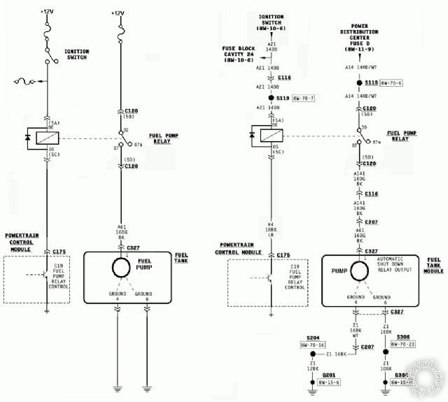
Posted By: issakar
Date Posted: October 12, 2010 at 7:30 AM
the 7v comes between connector 207 and connector 327. sorry I havn't posted back lately, again with the busy schedule. I hope to get back at this tomorrow as it starts my "weekend". today is my "friday" so things are all weird.
Remember the other post you left about being here with no coffee? thats how I am right now, lol. I'm going to get myself some of that delicious awesomeness and try and wake up.
Thanks Oldspark!
Remember the other post you left about being here with no coffee? thats how I am right now, lol. I'm going to get myself some of that delicious awesomeness and try and wake up.
Thanks Oldspark!
Posted By: oldspark
Date Posted: October 12, 2010 at 8:03 AM
You druggie you!
You are driving (bad pun?) the schedule so no need to apologise for delays. I'm used to anxiously awaiting the latest outcome... (LOL!)
7V b/w 207 & 327???
They should both be the same voltage (less maybe some drop - but not 7V - maybe up to a volt or 2?)....
The voltage being ~12V when the relay is on, else GND with relay off because of Fuel-Tank GND #4 or #6 thru the unpowered fuel pump (ie, pulls "south of relay 5D/#87" to chassis/GND).
Paraphrasing....
With 5D/#87 jumpered to +12V - preferably (read: SHOULD be) via fuse - eg, say to fuse-D 8W-11-9....
Then 5D/#87 is ~12V.
And Fuel-Tank #1 C327 should also be ~12V (and the pump pumping).
So C327 in that circumstance is ~7V?
And C120 & C116 & C207 are ~12V?
Hence ~5V drop between C207 & C327? (Or 7V drop, whatever - ie, a BIG drop.)
If so, bad/thin cable else bad connection/s.
If mere corrosion, the "standard" pull-apart & reconnect all connectors should fix it. Else maybe some cleaning is required (friction rub, or contact cleaner, etc).
If contacts have been bad and hence heated, annealing and oxidisation may have ruined the contacts - replace else solder or a good joiner...
If I have misunderstood... my next coffee is due in about 9 hours...
FYI - remember that "finding heat" is a good way of finding bad or undersized contacts, connections, wires etc. The catches are (1) it assumes enough current gets through to cause heating, & (2) you have ice or burn cream handy - just in case...
Posted By: issakar
Date Posted: October 14, 2010 at 8:51 PM
Oldspark,
Just thought I'd tell you the good news. I got the truck rewired and running today. I need to button the wire back up and everything so i have some finishing work to do. but Its running. I cut the a61 wire and soldered a new wire in its place. the only thing i need to do is double check and make sure that wire didnt supply power to anything else beyond the fuel pump :-O this came as an after thought but if it does won't be a big issue, I will just spice the wire into the new wire.
Thank you SO MUCH for all your help, I am glad we got this figured out and fixed.
Thanks again my friend!
Posted By: oldspark
Date Posted: October 14, 2010 at 11:52 PM
GREAT! So a bad wire or connection.... (Not a "component" like a relay etc.)
But hopefully you can do a similar fault find in the future...
It's sort of simple once you understand a few basics. And have a DMM.
I recall some idiot saying it was (likely to be?) a faulty relay contact...
But both faults have the same "output" result, hence the need to drill down....
Well done issakar!!