charge 2 batteries with isolator?
Printed From: the12volt.com
Forum Name: General Discussion
Forum Discription: General Mobile Electronics Questions and Answers
URL: https://www.the12volt.com/installbay/forum_posts.asp?tid=125854
Printed Date: May 13, 2026 at 4:42 AM
Topic: charge 2 batteries with isolator?
Posted By: tresvatos
Subject: charge 2 batteries with isolator?
Date Posted: January 25, 2011 at 6:55 PM
I have a question about a dual battery set-up that I could use that would isolate a second ( stereo ) battery, from the
start battery while engine is off, such as an isolator would do. Although tThe question I have, is how could I charge both batteries from
a home charger, if the isolator seperates the batteries when engine is off? Thanks for your ideas
Replies:
Posted By: oldspark
Date Posted: January 25, 2011 at 7:24 PM
Why?
Otherwise, the same as usual.
Isolate BOTH batteries from their loads and connect them together.
Are you using a $5 UIBI (Ultimate Intelligence Battery Isolator), or a more expensive "smart isolator" etc?
The latter should connect the 2 batteries automatically when charging. (The UIBI requires an spdt/changeover switch unless already configured with optional controls.)
Let me know if this is another where a "bigger battery" was suggested over a bigger alternator.
If you are externally charging for other reasons, that's cool. (EG, total loss; faulty alternator; desulfation; etc.)
Posted By: tresvatos
Date Posted: January 25, 2011 at 10:34 PM
oh this is for a marine ( boat setup ).. It is usually a good idea to get on the water will fully charged batteries. I would like to use an isolator that would charge the stereo battery when engine is cranked, and also be able to charge the primary, and stereo ( second ) battery via a home charger. thanks
Posted By: oldspark
Date Posted: January 26, 2011 at 12:49 AM
But don't put the (salt) water on the batteries! (Ka-Bang! Or in marine-speak - Boat-Bang!) (Ha ha - as opposed to your " It is usually a good idea to get on the water will fully charged batteries".)
Being marine I assume a stator system or permanent magnet rotor etc - not the normal automotive current controlled rotor which has a charge lamp.
Hence you probably have a "Smart" battery isolator - aka voltage sensing - ie a relay controlled by a voltage sensing circuit. (A UIBI is a relay controlled by the charge light (circuit).)
Hence if you connect your charger to the main or first battery (that the marine alternator charges), the isolator should automatically connect the aux/2nd battery.
[ IE - when the marine engine charges, the main battery voltage goes above (say) 12.8V to 13.6-14.4V etc, hence closing the isolator.
The same thing when "home" charging the main battery - its voltage should exceed the isolator's turn-on or connect voltage, hence also charging the other battery.
Unless you have a bi-directional sensor, charging the 2nd or "dwwnstream" battery will NOT close the isolator. ]
The main reason for disconnecting loads when mains (AC, home) charging is to protect loads in case of high-voltage spikes etc. (I sometimes don't bother, but I have older vehicles (no EFI/EMS etc), know my charger, and rarely get lighting strikes etc.)
FYI: If your main battery is fairly discharged or you have a small home charger, it may be that the voltage takes a while to rise above the isolator's connect voltage. That's not a problem.... (though max total charging would probably occur with both batteries connected)...
But when the 2nd battery connects, the voltage could drop thereby turning the isolator off. Then back on, then off, & on & off &....
But that's why "smart" isolators should have delays and hysteresis (eg: on at 13.5V, off at 12.8V). (Ahh - but what switching voltages, and how long the delays? LOL - the problems with "smart isolators". The UIBI has no such issues.)
tresvatos - I originally asked "Why?" thinking "another dumb application and implementation". 
Thanks for proving yet again that most posters and questions hereon are not like those I find elsewhere.
It is so nice merely confirming or explaining that yous already have the right idea or implementation etc. (No arguments etc - the only time-wasting is my " let's check every detail/assumption" rambling.)
Thanks for pulling my forum-day back & well into the positive! 
Posted By: tresvatos
Date Posted: January 26, 2011 at 12:50 PM
Thank you.. I believe that post above answered my question. My next order of business is to find a smart isolator that will connect the parallel circuit when the primary start battery is charged sufficiently. I am using Optima Brand Marine batteries as well in this set-up.
Posted By: oldspark
Date Posted: January 26, 2011 at 3:37 PM
tresvatos wrote:
.... a smart isolator that will connect the parallel circuit when the primary start battery is charged sufficiently.
No such thing! Well, not without current sensing at the main battery or VERY sophisticated AC diagnostics!
They simply connect when the voltage exceeds their "connect" threshold, and that should happen within seconds of charging irrespective of how flat the main battery is. (Unless the alternator cannot supply the total load.)
That is generally the best behaviour anyway because that is the MAXIMUM total charge replacement in the quickest time (and with least battery wear).
In fact I don't know why they bother with advertising their alleged "prioritisation" when that is worse for the system - unless perhaps you consistently crank and only run for a few minutes...
Many claim such battery prioritisation - eg - see the video for Projecta's 12 Volt Electronic Dual Battery System for their DBC100K etc. If that has any truth to it, please explain how the "two wire" voltage sensor determines the main battery's state of charge!
Alas the extra extra cow dung can have a huge inflationary effect on isolator prices!
I'd consider using the MW728 (~$20) though I might increase its dropout voltage from 11.2V (with series diode(s) and a small relay if the "on" voltage is not to increase by the same amount).
The MW728 drives whatever "plain" relay you want to use (it can supply 10A). (aka a UIBI using an MW728 instead of a charge light!)
The main snag is whether the timing/delays of the MW728 are suitable.
But otherwise get a reputable isolator - forget their hype, read what others say. And probably just buy on lowest price with adequate current capacity.
(Noting that the current can be increase by simply adding a bigger relay - is, the isolator or MW728 energised the relay instead of connecting the batteries.)
Hopefully dispelling "priority charging" - and the need for it - will save you a $hundred or two!
And I just realised - that Projecta bullsh is an Australian site. Another $10,000 fine coming up? Does anyone want to sue? LOL! I like suckers that think we are suckers!
Posted By: tresvatos
Date Posted: January 28, 2011 at 12:03 AM
I understand exactly what you mean with the voltage sensor cutting on -off-on-off.. I am wondering now if the circcuit may be easier and simple if i were to just put a switch to trigger a relay to connect two 12 volt batterie in parallel.. I could just flip a switch when I want to use one battery to power the stereo and accessories while the engine is not running..
Posted By: oldspark
Date Posted: January 28, 2011 at 5:33 AM
That is the manual way... But should you forget....
But it sounds like you have tasted one of the drawbacks with the voltage sensing units.
Not only are different voltage levels desirable (eg, disconnect at 12.8V if NOT charging but maybe 12.0V if charging), but also different delays depending on the reason (cranking, indicator or other "sags").
My MW728 was oscillating on-off at about 15-30 second intervals with a ~5A load despite the #2 ~60AH battery being fully pre-charged on an 8A charger. (Engine was NOT running/charging.)
But that ceased after a short run - the alternator's 14.4V at whatever Amps (up to ~75A less ~20A max for the vehicle) presumably blowing away the cobwebs (ie, soft-sulfite) of the 2nd battery.
Hence the advantage of the UIBI (charge-light controlled).
But voltage-sensor delays can be extended to many tens of seconds.
Before the UIBI, I had a "smart" isolator to connect the 2nd battery, but that was a $22 kit with an 80A "latching" relay. (Hence the circuit only drew 4uA except when toggling the relay. Or higher if using the flashing status LED.)
Its voltage is easily changed as per kit instructions - eg for 12 or 24V operation, or as a "high voltage connect" or "low voltage disconnect". [The former being a "smart battery isolator", the latter a "battery protector" to disconnect the load before excessive battery flattening. (Never use 555 timers for that unles they disconnect themselves, and their 10mA draw is ok!)]
I still use that kit as my low-voltage cutout (ie, isolate the load if battery #2 gets too flat), but the front "high-voltage cut-in" is now replaced with a $10 relay (~140A capacity) connected to the alternator charge light terminal.
The point being...?
Oh yes - the kit explains the circuit operation and the various delays. (I shied to it the same way ImAnIdiot shies to my l o n g explanations.) But it should be possible to vary the delays... (The kit is the Oatley Electronics AUD$22 K227 - 12-24V DUAL BATTERY ADAPTER FOR A VEHICLE. Consider a spare 80A latching relay for another AUD$6.50 RL8. NOTE that it is the PCB, components and relay only - not the case nor connectors.)
Alas I've been meaning to re-examine that explanation...
There is also the "cig socket" 10A MW-728 which is available for under $20 here (Australia). (If 10A isn't enough, use it to control a bigger relay. Snip off the cig plug & socket as desired.)
It is based on an LM3900 or similar "quad comparator" or op-amp (distant memories...) and equivalent circuits are not difficult to build (provided you have the circuit). Not that I condone reverse engineering brilliant and successful commercial products (that's why I suggested the Oatley kit), but DIYers might be keen to modify an MW-728 to suit their voltage & delay requirements....
(FYI - for the price of an MW728, it is NOT worth "ripping off" to do it cheaper!)
Anyhow, a manual switch saves you about $250 for a Projecta 100A "smart priority charging" male-Bovine-dung isolator if bought here in Aus.
Cheaper isolators here are usually $80 upwards. (That's why I used the $22 Oatley kits!!) [Dare I mention a "Redarc" isolator that claims better "battery charging" from its 80A isolator than a straight relay of 140A or higher rating? Yes - that confuses me too - it does NOT include a dc-dc converter - they cost $300 for 20A and $500 for 40A (from other suppliers - and all Aussies know you must have a dc-dc converter to properly charge your second battery. TRUE! - I've read it on Aussie web sites!! {Yes, seemingly unscrupulous commercial sites.}).]
Selecting a "smart isolator" depends on what you want.
BlueSea include a starter input (to parallel batteries during cranking).
Several offer variable voltages for both connect & disconnect. (There must be some hysteresis - the MW729 f.ex is typically 11.2V & 12.5V.)
BTW - increase "fixed" voltages with diodes - eg, add a 0.2V Germanium or 0.3V Shottky or 0.6V normal diode to boost the 11.2V MW728 "cutout" to 11.4, 11.5, 11.8, 11.2+0.6+0.6=) 12.4V etc. Use an output-controlled SPDT relay to short out some or all of those diodes for a 12.5 or 12.7, 12.8, 13.2V etc "cut in" voltage. The diodes are inserted in the ground from the sensor (MW728) and the supply (cig-plug to socket).
So many possibilities - all cheap "building blocks" - albeit with some "simple" electronics (diodes & relays).
Posted By: tresvatos
Date Posted: February 13, 2011 at 9:54 PM
I have decided to use a battery combiner..this will disconnect the parallel circuit between the two batteries when voltage at the starting battery drops below 13.3 volts and lets the other battey that stereo amp cables are connected to reamain supplying power. My question now is can a RED top Optima starting battery, and a BLUE top Deep cycle be wired in parallel..?? I have heard not to parallel two unlike type batteries, and then I have heard it will not affect the batteries..so that is my question..thanks
Posted By: oldspark
Date Posted: February 14, 2011 at 3:52 AM
Battery Combiner... Smart Isolator - same thing.
Paralleling different batteries when charging does not matter - ie, blue, red, pink, wet, AGM, new, old, 35AH, 100AH etc. (As long as same voltage (12V) and lead-acid.)
It would only be if that clashes with manufacturer requirements. EG - if the reckon their battery needs 14.6V charging as opposed to the normal max of 14.4V etc.
If paralleling when not charging (and to a lesser extent - when being loaded) then matching batteries becomes important - but you are not in that situation.
Just be wary of using non-marine batteries in marine applications - ie, salt environments.
Posted By: tresvatos
Date Posted: February 14, 2011 at 6:18 AM
thank you.. I hae done alot of reseach on the battery combiner, and it seems to be what I need. I will try to get another Blue Optima //Battery for marine use, I just asked the question above because I have a Red Optima available now. the marine Blue optima is designed exactly like the RED, just hs two more post for marine applications, other wise the Optimas are the same, just Deep Cycle, or Starting
Posted By: oldspark
Date Posted: February 14, 2011 at 8:48 AM
Great.
Again, being marine, you probably do not have the UIBI (charge light) option - hence a smart isolator (ie, a low voltage isolator or high-voltage combiner - same thing).
Nice to see a relatively high disconnect voltage (13.3V) - usually they are below 12.6-12.8V which means connected until slightly discharged; but such low voltages are chosen to prevent false-drop outs due to transient loads (brake lights, wipers) unless time delays cover it...
But that's the switching problems we wrote of earlier....
Other than "marine hardening", the red or blue should not matter.
And since Optimas are AGM, salt reaching the plates or acid is not an issue (bang!).
But if "marine" also means different terminal metallurgy....
tresvatos - thanks for your reply.
Thanks too for using an isolator. Although you want it anyhow for battery independence (a good idea for marine - it's a bit hard push-starting or finding a suitable slope, and it's somewhat more critical than for land vehicles!), I like it simply to extend battery life - especially after ONE of the batteries has failed (ie, and brings down the other one)!
After an isolator, the only thing required for complete security & maintenance is a voltmeter. Backlit LCDs are probably best. I use a blue=LED in my car.
(Voltmeters are one application where I think digital is good; 4-digit for accuracy BUT only 3-digit if on a visible console - eg, 14.2V on my dash instead of a flickering 14.23V etc. Otherwise an analog meter or expanded-scale meter (eg, 8-16V) is also good & has minimal draw - typically a few uA.)
Whether 2 voltmeters or one switched voltmeter, I can check battery status and tell if one is failing....
I can also confirm suitable charging voltage (not too high, not too low...)
Again tresvatos - thanks. And congratulations.
Good design!
Posted By: tresvatos
Date Posted: February 23, 2011 at 4:17 PM
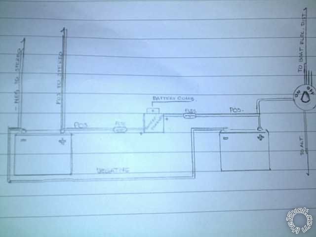 I have decided to use a Battery combiner as pictured above between two Optima Batteries ( deep Cycle/starting ) Does anyone see a problem with the diagram..? I need to find out a place to get the remote (ignition on ) pos wire to turn on my Stereo headunit..Should I get that wire from the right side BAtt that id conected to the Boat main on-off switch, so that it powers up when the boat main switch is turn to ON..? Thanks
Posted By: oldspark
Date Posted: February 23, 2011 at 6:13 PM
The battery fuses should be at the battery terminals (diagrammatically - ie, protect ALL attached cables) not near the isolator.
Where is the battery GND for charging?
Not sure why you want he manual isolator - unless that is already there (as part of normal marine installations or safety procedures).
I'd assume you'd want the HU to be powered from the manual switch's ON position (otherwise you risk draining the RHS battery).
Are you voltage sensing for the isolator, or manual switching? If manual, with low-voltage protection?)
And I guess cranker on the right with deep cycle on the left.... (or are these the "both" cranking and deep cycle batteries?)
Posted By: tresvatos
Date Posted: February 23, 2011 at 6:42 PM
Yes I found a smart isolator and I went ahead and decided to try that. It cuts circuit at 13.3 volts.. I am grounding to common engine ground, but forgot that in diagram..The headunit remote on should be to the reserve battery as well?? That makes sense, but I will need to put a switch to cut it on and off in order to provide power to the Head unit remote/ignition on whereas it would come on with main battery switch if I wired it to the master switch ON/OFF switch power pole.
Posted By: oldspark
Date Posted: February 24, 2011 at 1:42 AM
Good to see a high switch-off smart isolator. Many are as low as 12.5 (and lower) which means 20% discharge. Few are above 13.0V.
I would have assumed the HU remote was powered off the main battery, but with a smart isolator it make more sense to be off the reserve battery to avoid flattening the main.
Posted By: tresvatos
Date Posted: February 24, 2011 at 1:06 PM
Thanks! that is wat I will try until it poses an inconvienance.
Posted By: tresvatos
Date Posted: February 24, 2011 at 4:12 PM
Thank you ..I have found a used Optima battery that has 15.7 Amp-hours when loaded at about 20Amps and a rating of 10 Cold crank Amps after loaded for 15 seconds of trying to crank an engine simulator. Would this Optima be worth the trouble to purchase, or should I opt for a brand new one? Thansk
Posted By: oldspark
Date Posted: February 25, 2011 at 4:20 AM
That rating does not make sense. A 15AH battery is small and would never be charged at 20A (for long, or with valid warranty).
They use 15AH (C20) batteries in emergency starter packs. I reckon they have more than 10CCA.
From what I have seen, Kinetic are recommended over Optima in the states (or Deka down here in Aus).
As to size, I don't recall any dimensioning info - what your load is, what reserve time you want etc. The general tip is do not discharge crankers below 20% and deep-cycle below 50% discharged (ie, 80% & 50% remaining).
Posted By: tresvatos
Date Posted: February 25, 2011 at 5:45 AM
Do these figures help explain a little better about the condition of this battery that I am contemplating purchasing? It measures in at 15.7 Amp-hours when loaded at about 20Amps. Using an inverter with two 100W lightbulbs. It ran for about 45 minutes. A new battery would measure about 38Ahr for this test.
A Cold Cranking test using a carbon pile load, after the battery had discharged at least 6 amp hours. The CCA test consisted of a 350Amp load applied for 15 seconds. The voltage had to be at or above 9.6V at the end of the test. The CCA test passed with an end voltage of 10V. Also, I tested it using a PulseTech 490PT Battery Conductance Analyzer and it passed. Thanks for your help! Greg
Posted By: oldspark
Date Posted: February 25, 2011 at 9:15 AM
15.7AH at what rate? (C1, C10, C100?)
Or - how are you measuring AH? Do you mean Amps? (IE - 200W out should be about 20A, but it actually measured 15.7A???)
350A for 15 seconds is ~1.5AH, but assigning AH to a CCA test is meaningless - ESPECIALLY for a small battery.
Instead, charge the battery and test it at its rated load - eg, 785mA for 20 hours - and confirm its end voltage.
Or test it with the intended load until it hits its desired end voltage (20% or 50% etc) and decide if that is long enough....
But a bigger battery will last longer (lifecycle wise) if you use it for the same load for the same time - ie, the lesser depth you discharge a battery, the longer it will last.
[ The less current you discharge and charge with, and faster you recharge it (after discharging), the longer the battery will last. And the less often you recharge it the longer it will last - ie, constant float is best - but you "must" recharge ASAP after discharge. These lifecycle considerations exclude specific reconditioning maintenance - eg, equalisation or >20A desulfation etc.
Posted By: tresvatos
Date Posted: March 08, 2011 at 1:21 AM
Well sorry for the delayed response, but I have decided rather than risk using an old battery, I just went ahead and purchased a nEW yellow top Optima to use in my boat for the stereo system.. The Blue ( Marine ) and Yellow, are essentially the same with only the battery post a little different for marine apps. Now alot of people on stereo forums are telling me the regular Deep Cycle ACID batteries work better for long periods of listening to a stereo without any charge, or work better than the Optimas multi-use crank/deep cycle.. I already have the optima, but I have a fairly new Deep Cycle in my garage also. So now my questions moves to should I use the Optima Crank/Deep Cycle Yellow, or a Plane ACID Deep Cycle for an hour-two hours of stereo use with no charge.. Remember this will be paralled via a smart voltage reg circuit (combiner-isolator )to an Optima Blue Crank/Deep Cycle. Thanks for your help!
Posted By: oldspark
Date Posted: March 08, 2011 at 2:54 AM
I thought wet batteries were not recommended for marine use (salt, chlorine, etc).
When not isolated, it won't matter (ie, when charging) assuming the charge voltage is appropriate.
Strange what those audio forums suggested - they seem to do the opposite of what I normally consider to be good advice - eg, suggest AGMs when there is a high current demand...
If you are not going to recharge a fairly flat battery for a while, then a wet is probably the best choice. (It can be de-sulfated etc.) That is probably why they recommended the wet over an AGM.
I rarely meet people that recommend Optima.
Posted By: tresvatos
Date Posted: March 11, 2011 at 10:22 PM
thanks for all the kind help! My next question is I have some steel cable used in aircraft( helicopter ) for the battery connections, being that I'm an aircraft mech. Would this work alright as a Ground cable in parallel circuit, or would copper be a much better option?? I always thought aircraft had the most optimal equip available, but I read that copper was alot better contuctor.
Posted By: Ween
Date Posted: March 11, 2011 at 10:56 PM
do not use steel cable.
googling electrical conductivity shows copper being a rather close second to silver with steel far down on the list.
mark
Posted By: oldspark
Date Posted: March 12, 2011 at 12:18 AM
Steel? I would have thought aluminium for lightness, though that's even worse than copper for fatigue and creep.
Copper is the best conductor - beaten only by silver, but better than gold, ~30%(??) better than aly, and heaps better than steel.
Steel is probably used in choppers - and helicopters - 'cos of vibration....
Posted By: tresvatos
Date Posted: March 12, 2011 at 3:55 AM
I bet you are right..I have never thought about that..I ws really curious why steel was being used in Multi Million dollar aircraft......I imagine that would be the reason, because of the vibration theat it is subjected to
Posted By: tresvatos
Date Posted: March 29, 2011 at 2:48 PM
my question now is would it hurt to have my reserve\house battery remain the one that i have now since all my stereo and lights are wired to it and on that side of my boat. If I do that I will place my starting battery on the other side of my boat with a long 4 ga. Wire running back to the main off\on switch which goes to the starter...basically backtracking with cable to where my original starter battery was located..I am using a smart combiner between the two batteries also ..thanks
Posted By: oldspark
Date Posted: March 29, 2011 at 3:42 PM
Generally in vehicles, people (should) keep their normal (wet) battery for starting etc, and additional AGMs are used for the added loads (audio etc).
This is for a combination of reasons including that AGMs do not like supplying high currents (cranking), and why have a low-resistance AGM far from the load (amplifiers)?
Since an isolator is being used, battery symmetry does not matter - ie, matched batteries; symmetrical interconnections and discharge currents. (They both charge at whatever rate they can, and each discharges its own load.)
So which battery where is one of life or performance...
Posted By: tresvatos
Date Posted: March 29, 2011 at 7:02 PM
yeah question is somewhat ambiguous..i guess to ask a simple version of the above question would be if it would matter if the starting battery were close ( 1\2 meter), or further ( 1 +1\2 meter) from main switch that supplies starter..this is using a 4 ga heavy cable..It woyld make sense to have closer but i would have to rewire my boat to place stereo and utility popwer wires to the otherside which would be a major project. Thank you for the wealth of knowledge
Posted By: oldspark
Date Posted: March 29, 2011 at 7:27 PM
Probably not....
There'll be 3x the voltage drop... (LOL?) ie, 1/2 versus 1+1/2 - but that is no big deal if (1) the 4G is good enough & (2) it is the same overall length of 4G or equivalent. (That started more as a LOL, but it has some trivial seriousness....)
4G sounds small for a starter cable, but cable ratings are for steady or long term use whereas cranking is short....
The tell-tale is if the cable gets too hot (warm is normal) or if the voltage drop is so great that it doesn't crank properly. (Be aware that the battery may drop a lot too - a good 12.7V battery may dip below 11.0V etc.)
The only other distance impact is for protection. Not that starters are normally fused, but if (say) the switch is a form of protection, now it is 3x the distance from the battery.
But if physically secure - ie, negligible risk of a short etc, then that's ok.
Starter motors are usually not fused because their cable etc is considered physically secure/safe (at least with standard lead-posted batteries where the post can be the ultimate but unintentional & undesirable fusing point).
It is the "[physical secureness" and its risk of failure that determines what is the acceptable distance from a battery and fuse etc. (I often see quoted max 6" or 18" between battery and fuse without regard to the type/size of battery and layout - as if there is some magical fixed distance that applies. The magical distance is so (there is acceptable risk) that "no short/fault happens between the power source (battery) and the fuse".
Posted By: tresvatos
Date Posted: April 04, 2011 at 3:26 PM
Well I did find out that the aircraft cable is actually tinned copper, so that makes me feel better.. Glad I found that out.. I had asked about that earlier since i have access to that cable.. I originally thought it was Steel because it looked like it from the outside..
Posted By: oldspark
Date Posted: April 04, 2011 at 5:50 PM
That makes sense!
The best conductivity but tinned for solderability or maybe less termination corrosion.
Tell them to start using gold instead - even less corrosion - that's unless you cease having access to it....
Thanks for clarifying.... Steel did seem weird... (Did I suggest fatigue? Hmmm)
|