Hi, I am in the process of designing a circuit for automatic headlights. This has been done before, but I want dual activation (one for parkers, and one for headlights).
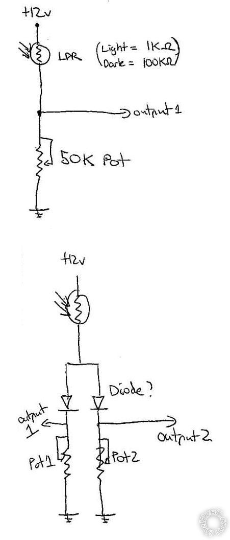
I am using a LDR (light dependent resistor) and have one leg connected to +12v, and one leg connected to a potentiometer to adjust its sensitivity which is connected to ground. The output of the voltage divider is the middle of the two components. This works great, and can trigger one of the circuits with no issues. (see top diagram)
I want to try and use the one LDR and have two separate outputs, which are each controlled by their own pot. (one will be parkers; Semi-Dark, and the other will be headlights on; Dark).
I have tried diodes, but it doesnt seem to work as I want it to (see bottom diagram)..
Can anyone enlighten me on how to do this? I want to avoid having 2 light sensors, as the light sensor has already been installed in the dash of my car.
Regards Tony.
-------------
Run a fixed resistor on the bottom of the voltage divider.
Feed the voltage output of the divider in to two separate op amps. Set each op amp up in a comparator fashion. Each comparator will have it's own pot to adjust sensitivity.
Should work well.
-------------
Kevin Pierson
https://www.bcae1.com/opamp.htm About 1/3 of the way down the page. Op Amp as a Comparator
Thank you for the heads up and help.
I have ordered a few op-amps, and a few dual op-amps so I can learn with and implement into the circuit.
I will post up the entire circuit with delay feature for comment soon..
The idea is:
One LDR feeding 2 Op amps which drive 2 separate Schmitt triggers (useful for the hysteresis window) which then feed into 2 NPN transistor bases (with caps and pots controlling the time the NPNs stays open (ideally around 30 seconds, so that the lights dont flick off if subject to a bright light condition at night for a short period of time).