oldspark battery bank w/possible solar
Printed From: the12volt.comForum Name: General Discussion
Forum Discription: General Mobile Electronics Questions and Answers
URL: https://www.the12volt.com/installbay/forum_posts.asp?tid=127317
Printed Date: May 15, 2026 at 4:51 AM
Topic: oldspark battery bank w/possible solar
Posted By: meltmanbob
Subject: oldspark battery bank w/possible solar
Date Posted: May 13, 2011 at 1:14 AM
Situation -
I could write a lot here, if anyone is interested I can expand more. Simply put I am buying a van to live out of for the next year while cramming almost 2 years of classes in less than a year so I can transfer into an Electrical Engineering program. Money and time are limited so I have to make sure they are used where it counts most. Summer starts June 6th and I need to figure out how to provide power to the van for small appliances and a computer.
The vehicle -
1991 Ford E 150 extended conversion van, comes with a 13,500 BTU A/C on top and a 2,500w industrial power inverter. The inverter was meant to replace the small generators on big rigs for power while they are camped and supposedly costs a couple thousand new, apparently it can power the A/C unit.
My goals -
- Stealth
- Be self sufficient
- Power small appliances and computer, ie a mini mini RV
- Be power efficient as much as possible, ie don't run the 5.7L engine a whole lot just to recharge batteries
Electricity use per day - expected/max -
A/C (1800w) - 0hr/1hr - 0w/1800wh
Mini fridge (42w) - 24hr - ~1000wh
PC w/monitor (~350w) - 2hr/4hr - 700wh/1200wh
Hot Plate (1500w) - 1/4hr/3/4hr - 375wh/1125wh
Toaster Oven (1500w) - 0hr/1/2hr - 0wh/750wh
Other - ??hr - 200wh/400wh
The rest of the stuff would be some lighting, cell phone, cordless power tool battery chargers, AA/AAA battery charger, occasional car vacuum etc.
Total per day - 2275wh/6275wh
Average use per hour - ~95w/~262w
---------T-105--------------T-145----------T-105---T-145---T-105-----T-145
------------------Capacity---------------------C/10 Amps--------C/10 Watts
2-(225AH/2700w)-(245AH/2940w)---22.5A---24.5A---310.5w---338.1 w
4-(450AH/5400w)-(490AH/5880w)---45A-----49--A----621w------676.2 w
6-(675AH/8100w)-(735AH/8820w)---67.5A---73.5A---931.5w---1014.3w
The plan so far -
-Purchase 2-6 used Trojan T-105(225AH@20hr)($55ea plus core) or T-145(245AH@20hr)($60ea plus core) 6v deep cycle batteries for an effective 1-3 12v deep cycle batteries.
-Possibly upgrade the alternator to a 130 or 160 amp along with the "Big Three" wires.
-Move some existing loads to the battery bank such as the radio, power inverter and lighting.
-Run most non essential vehicle loads off of the inverter, ie A/C, PC, mini fridge etc.
-Potentially install smaller secondary inverter for the PC - see questions.
Questions -
- Do I need to worry about the safety of the PC if I turn on the A/C while the PC and mini fridge are on? Those 3 items are very close to the inverters rating.
- Do I need to do anything special for the PC to protect it from start up current when other items are turned on or when the vehicle is started?
- How many batteries should I get? I think 4 of the T-145's should work so long as I have a way to recharge them, I don't see the electrical load draining the batteries more than half of their capacity from any one peak usage which would be cooking times or when the A/C is used.
- Should I avoid the used batteries I have mentioned?
- Will a UIBI set up work or do I have to worry about the battery bank pulling the starting batteries charge down to unacceptable levels once the van is started since I will only be driving short distances?
- What are the thoughts on Wal Mart deep cycle batteries since it would be very easy to exchange when they crap out and most likely not cost much?
- What are the thought on adding a solar panel or two?
I see three options - use the engine, buy and use a generator or buy and use solar panels. Solar seems the best option since it will probably be no more expensive than a generator, probably cheaper than a purpose built quiet generator, cheaper in the long run over running the van, and would be the quietest option of all. The down side is limited space, limited daylight and power recharge capacity.
- What are the thoughts on DIY solar panels over pre-made regarding total cost, time invested and functional benefits?
Other Thoughts -
I've worked at a car audio shop briefly when I was about 17, I've worked as a field tech for a cable company for a few years and as an electrician apprentice for a few years plus I had some electronics training in the Air Force. I'm not very good with designing electronic circuits but I can do all of the basic stuff, just need some help figuring out what I should be doing to accomplish these goals.
Replies:
Posted By: oldspark
Date Posted: May 13, 2011 at 2:04 AM
I'd probably forget solar... 92W/hr means at least 400W of panels assuming 50% daytime and 50% of "full power" (cloudy etc).
Then the battery capacity to be able to be charged at those rates...
And assuming a few dark and rainy days....
I'd suggest get rid of your hotplate and toaster. Electricity is not efficient for heat - unless using a reverse cycle aironditioner!
Use gas (propane etc) or petrol or wood or engine/exhaust heat instead.
And reduce your fridge power unless it is large and a compressor type. (Forget Peltier & 3-way fridges off battery power! I bought a >$1000 40L fridge rather than another >$750 of panels etc for my $145 heating/cooling Peltier fridge - but now I can have ice-cream in 45°C (115°F) heat running 2.5A max but probably only 1.5A cyclic.
I also bought a 2.8kVA petrol generator (a used "CHonda") for $220 after deciding a >2kVA inverter and the battery drain wasn't worth while for my girlfriend's chainsaw (electric; ~1100W).
Plus of course a generator has essentially infinite reserve time compared to batteries (depending on petrol supply). And it has a 12V 10A output (in addition to the AC 2.8kVA).
I'll let you consider that before detailing further.
As to batteries, one tries to avoid series batteries, but parallel even more. Hence a big 12V battery is ideal, otherwise 2 series 6V.
If a choice between fore x 6V in series/parallel and 6 x 2V in series, I'd go the 2V route. But I'd also consider several parallel 12V batteries merely to keep to standard and interchangeable batteries because I know what's required for max life - but that might still not be IMO practical.
And battery sizing... A deep cycle may last 300 cycles to 80%; 1200 cycles to 50%, and 2500 cycles to 20% discharged.
It will last longer if charged slower, and if discharged slower, and if kept cooler.
And one has to decide what reserve time - ie, how long between full recharges and at what current drain...
Then details like max current draw and max recharge current come into it.
Also flooded (wet cell) batteries are probably the best (also economical) battery provided they are suitable... (ie, not "indoors" etc).
Posted By: meltmanbob
Date Posted: May 13, 2011 at 8:42 AM
Before getting into the solar you recommended doing away with the electric hot plate and toaster oven, how safe do you think that would be to run propane inside the van? If that is viable I am welcome to it although I don't know of a toaster oven that will run on propane which I would only have for pizzas and bagels. The hot plate I think would be fine to replace with a dual cook top propane burner. Again setting up camp to any extent outside of the van is very undesirable because there are a lot of stuck up people here who are entirely too privileged and wouldn't want someone doing that plus I have to worry about too much attention for the sake of not getting the van stolen. There aren't any places reasonably close where that sort of stuff is appropriate such as the beach so cooking with fire is out of the question unless you have some very creative suggestion on the logistics of that, same goes for cooking with exhaust gas!
As for the fridge I read an article somewhere that talked about using a thermostat to control when the compressor was turned on which was supposed to help reduce the electricity usage so I planned on looking into that but 42 watts seems small. The mini fridge would be in the 3-4 cubic foot range with a separate freezer door top just like a normal fridge so I can use the freezer for actual food storage instead of just ice cube trays.
Regarding batteries I am all ears, what would be some real world suggestions as opposed to putting 2 6v batteries in series and then paralleling pairs to get more capacity? Should I look into 12v Wal Mart deep cycle batteries? Why is it good to avoid series batteries and parallel even more so? Are you saying that the worst situation is to have a mix of series and parallel, the next worse is parallel, then series and then ideally in a perfect world a single battery of correct voltage and capacity? I was leaning towards the Trojan batteries because I've read they are better than the Wal Mart batteries but I like Wal Mart for the fact that they are everywhere and if one craps out I can take it back easily but I'm not so sure about the Trojans.
On to the solar, if I build them myself there are 40 cells putting out 1.8w each at .5v for about $47 on ebay. They are 3"x6" so if I strung 40 in a single column and had 4 columns that should easily fit on the van roof. That would be 288w @ 20v which I was reading should be used with a SMPS charging controller to make best use of the available solar power. Southern California is sunny most of the time so on the occasion that it is cloudy I will have to make up for it by running the van or some other means.
I'm sure this calculation isn't perfect but I figure it's close. Right now there is about 14hrs of sun, so integrating 144sin((pi*x)/7)+144 from -3.5 to 10.5 yields 2016watts, figure we're getting about 85% of full potential based on the max angle of the sun being close to 78 degrees which yields about 1750w over the day. So that leaves between 525w and 4525w to recover. 288w * 14hrs = ~4030w, 1750/4030 = ~43% efficiency based on usable sunlight, does that sound like it's in the ballpark?
If I can add a circuit to the fridge so it only kicks on based on the thermostat that sounds like I could save some energy. Actually thisthis describes getting a chest freezer to run on about 100w/day so I will look into that alternative so long as I can meet my size requirements.
I could replace the toaster oven with that Presto Pizzazz pizza maker since that's really the main thing I would want a toaster oven for, the pizzazz uses 1200w and supposedly cooks pizza's in 10-15min which means 300w savings off the top and reducing about half the time.
I could take your suggestion for the cook top using propane, my main reason for the cook top is boiling water and making the basics for burritos.
I can reduce my time on my computer as much as possible and try to get away with a simple dvd player for now, eventually I will build a new computer and because of the situation I'll factor in making it low power.
I could probably do without the A/C but I want to factor it in just in case, any thoughts out how long it would have to run to drop the temp in such a small space? I'm hoping that I could run it for 5min bursts here and there if absolutely needed.
So far that sounds like I could significantly reduce the energy required which I realize is going to be the most valuable aspect of this. Also I think it's safe to say that my max energy consumption can not be my max, I must make do with less.
I would still like to know what your suggestions are regarding batteries in terms of actual products and places to find them along with why you said that basically series and/or parallel set ups are undesirable.
Also the issues I mentioned before about negatively impacting the starting battery when the bank is connected while driving short distances and whether I need to worry about protecting the PC from additional loads being turned on.
Thanks for the quick reply and the help! I don't mean to sound rude or anything, just trying to understand why you are suggesting some of the things over others.
Posted By: awdeclipse
Date Posted: May 13, 2011 at 9:34 AM
Have you checked whether or not parking your van where you are intending to and living out of it will be "legal".
Posted By: meltmanbob
Date Posted: May 13, 2011 at 10:19 AM
I'm not sure if it is legal but knowing this area it probably isn't, these are the same kind of people that would outlaw being homeless, most of them really only care about keeping yuppie ville up to snuff. There is a good reason I've listed stealth as a main goal, minimize confrontation in all forms.
I am really curious as to what you were trying to get at with the light post...
Posted By: awdeclipse
Date Posted: May 13, 2011 at 1:13 PM
Posted By: meltmanbob
Date Posted: May 13, 2011 at 2:49 PM
Posted By: awdeclipse
Date Posted: May 13, 2011 at 3:25 PM
But since you are aiming towards electrical engineer keep away from the high voltage stuff. Good luck with school, all I can say I am glad I am done with all that.
Posted By: oldspark
Date Posted: May 13, 2011 at 5:05 PM
Fridge-wise, the question is what type is it. Compressor & 12V? If not, reconsider getting a 12V fridge - and not an absorbtion type (unless you intend to run that off gas) nor a Peltier type (ie, an electronic food cooler/heater).
As to batteries, a single monobloc battery is always the preference because all cells are co-manufactured and share the same history & temperature etc. That sums up the undesirability of series & paralleling batteries.
Series is undesirable due to charge inequality, but tends to be minimised due to equal thru-current, and easier to overcome.
Parallel is more undesirable for the same reason but has the disadvantage of unequal current distribution and mutual destruction if a cell or battery fails - which in turn can be a hazard.
There should be design tools available to give you an estimate of panel size for your locale and provide optimum mounting angle and direction.
The use of an MPPT should be well worth it. Like I said, I'd suggest a minimum of 400W based on half of 24 hours of daylight and 50% efficiency (of the sum - ie, clouds, rain etc).
Posted By: meltmanbob
Date Posted: May 13, 2011 at 8:26 PM
At any rate regardless of the van I end up in I now have to deal with the power inverter since the nice power inverter I've been talking about went away with the first van.
I may buy one large power inverter or I was considering purchasing a few smaller ones to get to about 2400w. Reason being is I have a cobra 800w power inverter that I bought for about $45 and 3 of those is cheaper than an equivalent single inverter. A lot at this point depends on how much I can get the van for.
Oldspark - I understand what you are saying about the batteries, do you know of a single battery that has the capacity I would need? What about batteries that could be joined in series only with no parallel connections?
Would another alternative be to put blocking diodes inline so that the current only goes one way? I'm just asking because I don't know of any single battery that would work or any large capacity 2v batteries for series only like you mentioned.
Posted By: oldspark
Date Posted: May 13, 2011 at 11:27 PM
I can't help with a battery since the final load & reserve time hasn't been determined.
But that would only be a size recommendation - you'd best seek advise from others wrt local supplies. We have no WallMart here and all I'd suggest is a particular flooded 110AH else Deka AGMs (aside from my own recommendations for Yuasa). Certainly Optima & Odyssey doe not fare well here. I hear that stateside, Kinetik are a good AGM.
BTW from earlier - you would only run a generator whilst you are there and have the extreme loads like hotplates etc, else need to charge the batteries.
And all fridges should have thermostats - how else do they regulate temperature?
Posted By: meltmanbob
Date Posted: May 14, 2011 at 12:24 AM
I think I want to shoot for the equivalent capacity of four of the Trojan batteries so roughly 450-525AH @ 12v. The A/C is no longer a factor and I will take your advice on the cook top using propane. That leaves mainly the computer and mini fridge along with small drain equipment such as cell phone charger etc.
Posted By: teenkertoy
Date Posted: May 16, 2011 at 11:31 PM
All this talk about matching batteries, series and parallel wiring, 6v and 12v makes me wonder why it's worth worrying over. I operated and maintained two broadcast vans (tv news style, mircowave antenna on a mast, etc). They used a setup very similar to what you want to build. We had a pair of marine deep cycle batteries with a 1kw inverter, and a 2kw generator for AC power. We also had a 40amp battery charger for shore power. All AC circuits had breakers, and all 12v DC circuits had fuses. Both 12v batteries were wired in parallel. We had a single battery fail twice (over 6 years), and neither time did it affect anything else in the system except for lowering the runtime of our gear.
One other consideration. Try to avoid as many transitions from DC to AC and so forth. If your batteries run the inverter, you have a loss of efficiency. If your desktop computer feeds off that AC inverter and converts back into DC, you have another loss. But if you have a laptop with a 12v car adapter, there are no conversions. Also if you have a fridge with a 12v adapter, there are less conversions. If you can use 12v lighting, so much the better.
-------------
Malcom: "This is the captain. We have a...little problem with our engine sequence, so we may experience some slight turbulence and then...explode."
Jayne: "We're gonna explode? I don't wanna explode.
Posted By: meltmanbob
Date Posted: May 17, 2011 at 1:44 AM
A laptop would be nice but that's another added expense and while the need for the computer will be school, it will also serve as my entertainment. The only thing that I do that bogs down my computer would be 3D magnetic modeling software, basic 3D CAD (SketchUP) or playing a game while having about 3 dozen browser tabs open in the background and music going. The summer is going to be extremely tough financially since there is very limited financial aid available, this is the last year they will do Pell grant and that's all that is available beyond getting my tuition covered. This wouldn't be such a big issue except I won't find out if I get any of the Pell grant until after school starts and I wouldn't receive any of that money until mid semester at the earliest. I have a lot to do to the van especially considering the one I wanted is no longer available.
For now I am going to try and under volt the cpu and gpu to bring the power down and I am considering getting a new monitor because the one I have is small and on it's last leg, if I get a new one I'll seriously consider an LED one for the low power consumption.
As time goes by I plan on adding individual voltage monitors for each battery and create my own charging circuit that can isolate each battery and charge each one individually and appropriately but that will have to wait until I find some people at school that could help like the robotics club guys.
It's good to hear that you have implemented a system similar to what I want to do and it worked out for you pretty well, I hope I have the same luck! I stopped by WalMart to check their deep cycle batteries but couldn't find any and they don't list them online so short of calling stores or going in to check I'll have a hard time finding them. I really would prefer to buy them there simply because of their return policy.
As far as the extra power conversions I hear what you're saying, if the laptop had a special built power pack that would be best, eventually I want to build a more efficient DC/DC psu but again that's down the road. A 12v "adapter" for a fridge wouldn't have any benefit if it's used on a 110/120v fridge, that's essentially what the inverter is already doing and from what I've read and been told the purpose built 12v fridges aren't great.
I will take your advice on the 12v lighting, I've been thinking of LEDs.
Something cool I found out from the guy who has this other van I may get is there is apparently quite a bit of room under the van along the driver side, enough to make a slide out rack for extra batteries!
Thanks for the reply and the useful info and suggestions!
Oldspark - This van that I may now end up buying doesn't seem to have a charge lamp indicator, what is your suggestion on setting up the charging system for extra batteries? Find a wire on the steering column ignition that only comes on when the van is running and use that for the relay? If I can find one like that do I need to use that to power a smaller relay to power the actual switching relay?
Posted By: oldspark
Date Posted: May 17, 2011 at 2:03 AM
teenkertoy wrote:teenkertoy - how long did it take you to figure out that one battery was bad? The problem is that since both batteries are at the same voltage, the good battery is dragged down and hence fails for the same reason as keeping batteries flat.
We had a single battery fail twice (over 6 years), and neither time did it affect anything else in the system except for lowering the runtime of our gear....
The drag-down may not be bad if it is merely a capacity drop (ie, the bad battery may still have its normal voltage), but if it's a collapsed cell, then the good 12.7V battery will reduce to 10.7V... The longer that exists, the more the damage. (Then there are also high-discharge rates and - especially for AGMs - the possibility of thermal problems and gassing.)
meltmanbob - as I wrote, I spent nearly $1,000 on another fridge because that was cheaper than not spending it. That $1,000 saved well over 5A of consumption at 12V - ie, 60W which meant another 100W panel and another battery (for a mere 12 hour reserve time).
If you don't have a charge lamp or similar signal (but alternators usually do, even if newer ECU-interactive DP types), then a voltage sensing system is required.
That's unless you are happy with manual control in which case I suggest the ACC circuit unless you do want the batteries paralleled during cranking (in which case the IGN circuit). But keep in mind that with IGN or ACC on and one battery goes flat, they all will - hence the desire for the automated isolating systems I have described.
Posted By: meltmanbob
Date Posted: May 17, 2011 at 4:16 AM
Regarding the charging system the guy said it was a 60 amp alternator and when I started the van I didn't see a dash lamp indicating when it was running on the battery or charging and running electrical off of the alternator. I think I got the IGN and ACC wires mixed up but I believe the description I gave was for the correct wire, just switched the labels.
Seems like either I missed something earlier in the thread by not getting on the same page or I'm just confused by the additional information.
The way I thought I understood it was this, charge lamp indicator is the same as the battery symbol indicator lamp on the dash. This is normally on unless the engine is running and only turns off at the end of cranking when the engine actually starts and all electrical load is now being carried by the alternator. The only other time it is not on is when the key is not in the ignition in any position but it is only not on the dash, essentially it is on but the lamp in the dash itself won't come on because the key has to be turned at least one position forward or backwards to let power flow through the dash lamp.
Now that I think about it this sounds as though there is a circuit from the battery to the dash lamp with 2 relays and is open. One relay is tied to the ignition key position so when you turn the key to some position other than off and haven't started the vehicle, it pulls the circuit closed and the dash lamp comes on. The second relay is tied to the alternator indicator but is closed which still allows the dash lamp to be on. When the car is started, assuming the alternator is not malfunctioning, the alternator starts up and powers up that wire and pulls the circuit open.
Does this sound right? If I thought about it some more I could probably figure out the same thing for the battery but I'm assuming it's very similar and I'm assuming that the description I just provided is accurate on principle but it's just speculation, let me know if I'm close or way off!
Posted By: oldspark
Date Posted: May 17, 2011 at 5:40 AM
The charge lamp as used by the UIBI (Ultimate Intelligence Battery Isolator - aka a relay energised by the charge lamp - the same wiring as many electric fuel-pump relays in carbureted cars) comes ON when ignition is first turned on.
It extinguishes when the alternator is charging - ie, after cranking and starting.
It will also come on if the engine stalls - ie, the alternator is no longer charging.
It is that circuit that is used for the UIBI.
The lamp only comes on when the IGN power is on. That's because the lamp's +12V side is the IGN +12V which usually powers gauges and some other dash/warning lamps (oil, temp, brakes, etc).
The lamp's other side goes to the L = chargeLamp circuit of the alternator. (This L-terminal is called D+ on "single-wire" alternators. Note that "single wire" does not include the standard HEAVY +12V to the battery nor the GROUND path through the alternator chassis to engine to ground etc.)
So, one side of the charge lamp is +12V.
The other side goes to the alternator (L or D+).
That L circuit is grounded when the alternator is NOT charging. Hence the charge light is lit - it has 12V across it.
When the alternator charges, its L circuit goes to +12V, hence +12V on BOTH sides of the charge lamp, hence 0V (zero Volts) across the charge lamp so it is therefore extinguished.
It's like the L terminal is connected to #30 of a SPDT relay (2-way aka changeover relay). The Normally Closed contact #87a of that relay is ground. The Normally Open contact #87 is +12V.
When the alternator charges, it energises that relay and swaps the L chargeLamp from #87a ground to #87 +12V.
I was searching for some simplified diagrams for the above, but I keep finding the same old "system" circuit from older the12volt posts - eg,
trailor alarm wiring (6th reply); adding a second battery (page 5, center); and stop starter motor once engine fires (page 2, center).
Some of the surrounding text might explain things better. And that "Regulator" depicts the changeover-relay type of alternator L/D+ circuit I have tried to describe.
There is a modern version of that diagram somewhere - it's the same but with the Aux battery moved to the LHS to highlight that the only thing added to the vehicle's wiring is the relay - the rest is standard vehicle stuff along with the additional Aux battery and its +12V cable and 2 fuses.
FYI - the same charge lamp circuit is often used to test certain dash warning lights when the ignition is first turned on - eg, brake fault, low fuel etc (but not high-beam, handbrake, flashers, oil pressure etc).
On older vehicles those tested lamps will be on whenever the ignition is on and the engine is not running (ie, the alternator is not charging).
On newer vehicles they might NOT come on after an engine stall because they use smarter dash-lamp management - only the charge lamp will light.
But I'll pause here for a while before explaining some further considerations - like if the L or D+ circuit is NOT powerful enough to energise the UIBI/relay)....
Until then, see if this reply clarifies anything.
And BTW - that relay could be a small or normal relay (15A or 30A) that energises bigger or more relays eg, one relay for each auxiliary battery.
Posted By: meltmanbob
Date Posted: May 17, 2011 at 6:28 AM
You mentioned separate relays for each battery, I'm sure there is a way to detect the actual voltage on each battery and use that to trigger the relays. Essentially they would have 2 relay conditions to meet, engine running signal from the alternator and then a voltage ok signal from some sensor. The question is can it be done easily with an analog circuit or does it require using micro controllers and programming. Any thoughts on this?
Also correct me if I'm wrong but wouldn't that only potentially protect from cell voltage degradation and not capacity degradation?
I wonder how you would keep track of capacity degradation, I'm assuming that's much more involved.
I guess the other part to voltage degradation is that you wouldn't be able to tell until you tried to charge it completely. In a situation like mine it could mask itself as not having had enough time to charge all the way and I might miss it because they would be constantly in use...
Posted By: oldspark
Date Posted: May 17, 2011 at 8:02 AM
Older external regulators used relays that could supply several Amps.
Internal regulators might supply a few Amps, but maybe far less - after all, they only have to "sink" highish currents - ie, GROUND a charge lamp and maybe other tested lamps (maybe 4 x 250mA bulbs = 1A etc), but they don't have to source high currents per se.
And then there are the very new alternators that might be designed to signal CPUs/ECU/EMS or LEDs etc, hence mere uAmps or mA....
And if overloading that L/D+ circuit ruins it....
(FYI - mine is currently faulty - my charge lamp and tested lamps do NOT come on. However, the alternator still charges fine. Many alternators MUST have a charge lamp (else those tested lamps in parallel) to provide a trickle/tickle current to ensure alternator charging - not that that means that circuit has to work.... Maybe mine has blown but still gets trickle current, or maybe mine does not need the charge lamp?)
(BTW - I'm not sure what blew mine, but I have also lost 2 other circuits, though I think that is mere coincidence. READ: I recently started to tidy up messy wiring. That IMO should NEVER be done if it works fine... If it works, leave it - ignore other peoples derogatory comments!)
HEY!! Stop conning me into un-pausing my aforementioned pause to discuss "weak" L/D+ circuits!
But yes - totally correct - a small relay to power a larger relay and then larger or more relays...
As to voltage sensing other batteries, I come back to "WHY?".
You cannot test the ACTUAL capacity of a battery from its terminal voltage. An old battery with 5% of its original capacity might still be 12.7V at its "now" full capacity - it will simply crash thru 12.6, 12.5, 12.4....11.7, 11.6V about 20 times quicker than it once did.
(To quote my old izu guru... "....(in practice) the only way to measure a battery's capacity is to discharge it with the desired load. And that does not mean it will do the same next time..." (ie, it could fail overnight). He then explained why critical batteries were therefore replaced after a certain time else a certain number of discharges. EG - critical UPS (Uninterruptable Power Supply) batteries with (say) a 10-year design life or warranty were replaced after 5 years - and even sooner if they had been used more often than intended! Yes - there are impedance measuring techniques, but they are too expensive and specialised for common use, and still merely a model.)
So back to voltage sensing... Why?
If your system is charging, then connect your batteries and charge them.
If you are not charging them, then isolate them to keep them independent UNLESS you want some or them to remain connected for whatever reason (ie, share a heavy load or provide longer reserve time).
And if you can find a TRUE priority charging system (ie, based on the actual charge state of the batteries - not merely a "let's wait a while before connecting"), then I will ask why do you want to take longer to get maximum charge into all the batteries?
Determining NOT to connect a battery because it is too flat or faulty is another issue. That can be managed, but it is very complicated - it really requires data-logging etc.
EG - you have 2 aux batteries at (say) 10.3V. One is fine but flat and hence wants recharging ASAP to minimise damage (ie, extend its life). The other is fully charged but one cell has collapsed.
How will your system decide not to connect the collapsed battery? And do you want to connect the other good but flat battery - what if its (initial?) charge current is too high? (What is "too high"?)
IMO the best (and only practical) intelligence is YOU.
All you need is a voltmeter.
And maybe some suitable fusing - though that might assume your recharge current is higher or equal to your max discharge current - unless you want to have current sensing that controls a relay/breaker (ie to trip at 20A charge current or 100A discharge current)?
Other than the voltmeter, INSPECTION.
Feel for heat; check for gassing; measure rested open-circuit voltages (for collapsed cells) - ie, not with surface charge present.
(Hence temperature alarms - a possibility but they must sense temperatures relative to ambient temperatures. Chargers might use temp sensing where a sudden increase in temp means the battery is fully charged - but that is when the charger is charging batteries... Batteries discharging into a load, in parallel...)
FYI - I have a 3 digit LED voltmeter in my dash. It sits across my battery: ie, -ve wire to battery-, and +ve wire to battery+ (although that is thru a relay which is IGN controlled but could be manually controlled or timed etc).
I don't monitor my UIBI connected aux battery because it is not in use - it merely sits & gets charged. I place a DMM across it now & then. The dash voltmeter would alert me if either battery took very heavy current. (75A alternator; 2 x 38AH AGM batteries that typically accept up to 45A at ~14.6V after cranking.)
I do have a great and cheap little LED voltmeter that could measure 5 or 6 batteries.
Intended for LiPo batteries in series, it requires one battery across its main terminals (GND and Batt#1) to power it.
It scans if other batteries are present (Batt#2, Batt#3 etc) and if so, displays their voltage With Respect To the main Batt#1 voltage.
Keep in mind it's intended for a series chain of LiPO batteries (about 4V each) but it handles up to about 24V.
But I haven't yet tested to see how it handles a -ve drop; ie, imagine 4 batteries with common ground at 12.4, 12.5, 12.0, 12.7V. The 12.4 is Batt#1 so it displays 12.4V. It then shows 0.1V for Batt#2 at 12.5V. Will it show -0.4V for Batt#3 (Batt#1-#3 = 12.4-12.0 = 0.4V) for Batt#3? It should show Batt#7 (12.7V) as 0.3V.
It's not ideal, but for a small unit costing a $few that can measure 5 or 6 voltages (I forget), I thought it worth getting a few.
Certainly handy for measure voltage drops along a path - eg, from alternator to aux battery or audio amp, power it (Batt#1) from the far end (amp or aux battery) and then successively connect Batts #2, #3, ... #6 inputs back to the alternator - ie, Batt#6 to alternator B+; the others at fuses or junctions in between. You would then see the "end" voltage (say 12.4V) and then all the voltage drops for each segment to the 14.4V alternator (displayed as 2.0V or 2.00V = 14.4-12.4V). THe target being to reduce each segment to 0V, hence te amp or aux battery equals the alternator voltage (so 14.4V, 0, 0, 0, 0, 0).
Woops - too complicated? And totally stupid - except for dorks like me that do things on the cheap (for multiple applications).
A practical equivalent would be dedicated voltmeters, else a voltmeter that is switched between different points with some label that indicates what is being measured.
IMO that is a PIC or PICAXE or uPC application with a suitable display - maybe an LCD with "Voltage drop from Aux fuse-to-battery+ is: 0.13V. And add datalogging. And an ammeter to log "0.13V @ 10.0A" and later "0.26V @ 20.1A" (hence R = 26mΩ)...
... (at 18May11 01:20; 13.7°C; altitude 132m; ...)
That's if you want to get into programming...
I have an Arduino that could do it - probably the cheapest way to do this sort of stuff...
Ready for another pause?
Posted By: meltmanbob
Date Posted: May 17, 2011 at 9:05 AM
Funny thing about wiring... I cut and extended pretty much every wire in my mustangs wiring harness... all at once but I labeled each one... not a single problem and it's been over a year and a half

As for the voltage sensing, I wasn't saying that it was a really great thing just that it could only possibly show you if a cell has gone bad but like you were saying in your posts, essentially knowing the voltage is only part of the picture. So I'm with you on the fact that you could have a normal voltage reading of 12v+ and still have a bad battery when it comes to capacity, I guess what I was getting at is ideally you would want a way to monitor voltage AND capacity to really have a better idea of how your batteries are doing.
Ok back to reading the post...
Ok whew...!
After reading that I want to add to what I was writing earlier, the voltage sensing would be meant only to detect a battery with a failed cell, I'll leave that at that since I think we're on the same page now!
I understand what you are saying about how essentially it is difficult or rather a very involved process to automate bad battery detection especially when you have many used together. Your example of 2 batteries with one having a bad cell and one being good but flat is exactly what I'm wondering about. Besides checking them on a regular basis are the only realistically effective ways to use a micro controller?
Everything I can think of would require data logging as you mentioned. With data logging you could track how fast the voltage is dropping on each battery which I'm assuming could be a pretty good indicator of a "bad" battery and by bad I mean one that at the very least is significantly under performing compared to the rest. I guess you would also have to track the power draw to extrapolate current draw or monitor current draw directly but they should be important in factoring in the expected efficiency otherwise a high draw run when compared to a low draw run would make possibly all of the batteries to appear "bad," essentially it would give perspective.
I'm not familiar with programming but that is part of the reason I am going to study electrical engineering. At least at the junior college level I will be taking all of the C programming language classes this fall and spring and I am going to try and have time to get into the robotics club since the engineering club there is kind of a joke in terms of kids that actually know how to put all that book smarts to use.
Before I forget, where can I find one of these voltmeters you have mentioned that can track multiple batteries?
My reasoning for eventually wanting to create a "smart" charger would be mainly for bad battery monitoring and charge them more efficiently. Maybe that's stupid or pointless but here is what I see being possible in an ideal situation:
Track engine RPM to calculate alternator max safe current output
Track individual battery voltages while operating and charging - bad cell detection
Track power and current draw individually - reducing capacity detection, limit or cut off batteries if drawing too much from alternator
Isolate batteries individually for charging that way if you end up not having enough time to charge all of them fully you won't have the less charged ones pulling the more charged ones down to where their voltage is not useful.
I'm sure I could think of more and I'm sure most of that would be a waste of time but that last one made me think of another question.
Here's the scenario - 1 starting battery, 1 or more reserve batteries. At least 1 if not more of the reserve batteries are significantly discharged needing say 2hrs @ c/10 charge rate. Start the vehicle which goes fine because the starting battery is fine, engine starts and reserves are connected to charge.
Question - Do the reserves start drawing most of the power from the alternator ie starve the starting battery and keep it from recharging from just starting the vehicle?
Also do the reserves draw power from the starting battery to try and reach equilibrium and only once that happens can the starting battery actually start to recover it's charge? To me it seems like at the very least the starting battery would be neglected until the reserves get closer to it and possibly get sucked down to their level.
There is something I'm obviously missing and don't understand about this situation so I'm just trying to clarify!
Oh the other thing about an ideal charger would be to sense when a battery should go to a trickle charge so a slower charging battery doesn't end up over charging one that's already charged. Again I'm speaking of what seems ideal, I don't have the knowledge or experience yet to know if that is actually practical or reasonably possible :)
On a side note I did want to say thank you for taking so much time to explain a lot of this stuff, most people don't both with such constructive conversations especially when educating someone who has lots of ignorant and big ideas!
Posted By: oldspark
Date Posted: May 17, 2011 at 11:23 AM
Forget building a charger, buy one - a 4-stage charger(3-stage for AGM).
And yes, battery condition can be done with a uPC. All you need is the required battery knowledge for the basic program (see BatteryFAQ etc), then add the battery size and all its relevant charge/discharge curves at different rates/loads and voltages & temperatures, compensate for else eliminate surface charge, then assign whatever values are considered to define bad or poor etc and decide what to do about it/them etc.
I'd suggest programming a EFI ECU or EMS first as that should be a good stepping stone.
IOW - IMO, forget it. Except for hobby reasons, it is not worth it - you will spend far more time programming etc than what you would ever spend manually monitoring.
Starve a battery?
If the voltage is above (say) 12.8V, you won't be discharging any battery (except for surface charge).
Below that you have a typical non-charging parallel battery situation which you may not want, so you isolate the problem else non-critical batteries.
Otherwise when charging, keep them all connected because that is the fastest way to obtain most total recharge power.
If the alternator is below its target voltage because of excessive load, then shed batteries if you have some reason for wanting some charged faster than others - eg, you want to wreck batteries faster by using a higher charge current, or your drive time or sun power is not enough to charge whatever battery enough (eg, the cranker for the next crank, or Aux#3 for the night's movie).
Float charge - when the battery's charge current reduces to whatever the manufacturer specifies as its float current (at whatever voltage, temp and after whatever charge profile (if that matters)), then it's fully charged and its voltage can be reduced to its float voltage (say 13.8V; maybe 13.2 for AGMs). That probably requires a PWM circuit if running from a charger that is supplying a higher voltage to charge other batteries. That reduces the voltage to that battery's loads.
But higher than float voltage is needed now and again to equalise the battery cells.
If the alternator can't handle the load, get a bigger alternator. (The voltmeter indicates the under-voltage in such situations.)
If the alternator is damaged due to over-current, then get a better quality alternator - eg, a purpose-built HO, not a rewound standard alternator.
Alternators should be self-limiting wrt to overloads. It should only be severe abuse that damages them (eg, my situation with nearly 60 minutes of using the starter to rotate the engine to un-bog the car whilst the aux battery powered a winch; several engine starts for short periods then back to cranking in gear... Even then the failure was because the alternator was so hot that the voltage sensing diode desoldered itself - the main diodes and windings etc were fine).
I just use my Oatley Electonics ~$25 solar regulator for my solar setup, though I am considering an MPPT (Oatley have one for ~$85).
As to float voltages etc, I used to think that 3 years from a car battery was good, but for the past decade or two I have been getting 6 years or more. That's on systems that are set to about 14.2-14.4V and do NOT seem to drop voltage even though the battery(s) should be getting hot in the engine bay. [If 25°C is max 14.4V charging with 13.8V float, then - from memory - 60°C means max ~13.0V charging (& ~12.5V float?). I do not recall seeing such voltages even when our ambient air temp is over 40°C, yet those batteries last >6 years. (They are the sole vehicle battery; flooded/wet cells; "semi sealed"; Calcium, with "Power Eye"; typically 1/4 to 1/3rd the price of similar capacity Optima AGM batteries.)]
For some reason I am reminded of distilled water in batteries. For years, using distilled water increased battery life by an average of ~3months. That was when batteries lasted probably 3 years. So a 1:12 life increment. Distilled water >$5. Battery ~$60. IE - break even. For the more typical $80 batteries, was it worth the trouble of buying and storing distilled water, and carrying it on long trips? IMO no.
As to my 6-year batteries... I opened their "semi sealed" cover after about 3 years and topped up with tap water. Maybe again a few years later.
Others go to so much more bother for little practical gain.
I think you will find the same thing for batteries. Mind you, there are people here that spend $300 to $500 for dc-dc converters so that they can "properly charge" their auxiliary batteries. However, I argue they have poor systems to start with, and they are so gullible anyhow.
I doubt that the12volt would recommend dc-dc converters to such people. the12volt would probably suggest The Big 3 instead, and then maybe a 5c diode to boost their alternator output voltage. (You can buy those diodes here off eBay, but they are mounted in an ATS/ATC fuse body and cost $35 plus $7 postage.)
(I wonder if thicker cables and a 5c diode are more reliable than a $500 40A dc-dc converter?) (That's a joke...)
Posted By: meltmanbob
Date Posted: May 17, 2011 at 1:35 PM
I think I know where I'm getting confused or need more clarification.
First let me ask approximately how much voltage is lost on a reserve battery when drained to half it's capacity?
When the reserve batteries are connected once the engine is running how long does it take for the voltage to recover? Does the voltage recover at roughly the same rate as the capacity?
I guess it would help me to know what the lower limits are of the reserve batteries when not fully charged, obviously they don't go to zero volts.
The way I was thinking about it was if I discharged the reserves to 50% and the voltage went from a full charge of 12.8v to 10.8v then it would take charging them back up to 75% capacity to get to about 11.8v.
So are you saying that regardless of how long the charging system is ran either engine or other means, once the reserves are disconnected then the voltage on the starting battery would be fine assuming it wasn't discharged any more than normal for starting the engine?
Assuming the starting battery was equal in capacity to one reserve battery then once they are connected to charge you would get 12.8v of the starting battery and say 10.8v of the reserves. If I remember correctly parallel calculation is 1/((1/x)+(1/y)+(1/z)...) so with 2 reserves at 10.8v you get ~3.8v ... nope something is wrong, math is right but wrong equation and logic.
Let me try and explain how my mind goes about understanding this from a basic perspective.
Starting battery and reserves are not connected...
Crank engine...
Electrons flow from ground through starter and to positive starting battery terminal - current has flowed, capacity has decreased, voltage has dropped due to the negative side becoming less negative and positive side becoming less positive ie less "pressure" across the dielectric...
Engine starts...
Alternator starts, reserve batteries join circuit - electrons flow through ground to negative battery terminals, batteries with the lowest voltage get more current (path of least resistance), as their voltage increases current decreases and distributes more equally to all batteries...
-as alternator spins it creates a rotating magnetic field pushing electrons through the ground, this can happen because the rotating field draws outer valence electrons from the neutral copper atoms on the positive sides of the batteries which make them more positive, more electrons are at the negative battery terminals and more positively charged atoms are at the positive terminal which creates even more "pull" or pressure across the battery ie voltage and "capacity"
-so long as the alternator is running it prevents current from going backwards through it like a short because of it's rectifier bridge
-when alternator is off it acts like an open circuit and minimal charge is lost
Essentially the negative terminals are like water towers, positive terminals are like lakes, water wants to flow with gravity and reach equilibrium, the alternator is like the pump that pumps water from the lake into the water tower but has a one way valve built in, distribution piping is like wiring from the battery to a device that needs power ie a washing machine needs water from the tower, the used water then returns to the lake...
So a higher charged battery when connected in parallel with a battery of lower charge and voltage will not help recharge the lesser battery from it's own capacity, it simply doesn't charge as fast as the lesser battery at first because it has a higher resistance to being charged at that point. To sum that up, the lowest charged battery will take charging priority although the lowest charged battery at any given time during charging may not always be the same battery at a different point.
This still leaves the conclusion that the starting battery will not have much ability to be recharged after starting the engine if the reserves are much lower than it. This would be a problem if the starting battery was only capable of starting the vehicle once before needing to be recharged but most batteries are capable of cranking an engine long enough to equate to starting a vehicle multiple times, my current car battery can crank the engine for probably 30+ seconds conservatively before needing to be recharged. This means that even if I can't fully recharge the starting battery between the time I get up and get to school, it will have other opportunities throughout the day such as after my exercise class when I go to the van to make breakfast and let the engine run for 20-30 min. If that isn't enough then the solar panels while I'm in class, maybe make a smaller panel dedicated to just the starting battery.
OK! Am I close? LMAO I gotta go check out another van but I think I logically reasoned my way through that to some sort of clarity, at least more than I had :) Let me know where I'm wrong or off about, that was just to try and help myself and help you see where I might be thinking about this the wrong way.
Posted By: oldspark
Date Posted: May 17, 2011 at 5:36 PM
Not that Bill (Darden) goes into paralleling of batteries (he cleverly fobs that off to other links) and similar issues, though I reckon I know what his view are. I also probably understand all the things he covers in a single simple sentence - ie, I now the all the sub-issues being taken into account in his "simple summary lines".
Discharge voltage - I use 0.1V = 10% (as a simple but conservative estimate).
Reality is usually from 12.6 to 12.7 (theory: 12.67V) down to about 11.4V @ 25 degrees C etc.
Voltage is proportional to capacity - but remember - that is Open Circuit rested voltage - ie, the battery's internal voltage (not terminal voltage when being charged o discharged). That 11.4V to 12.7V 0% to 100% is Open Circuit rested voltage.
Yes - a higher voltage battery will charge a lesser voltage battery, or rather, a lower voltage battery will discharge a higher one.
That's usually not a problem if followed by charging except for the added inefficiency (say 30% or more) or if currents are too high.
How long to recharge? Depends on the battery and the alternator voltage (and alternator's driving/RPM profile).
Most automotive batteries probably have 90% of their LOST charge replaced within 5-10 minutes.
You can't use parallel resistance rules for batteries.
A 12.7V & 10.8V will be somewhere between those 2 voltages.
But an OC 10.8V battery is probably damaged - 100% discharged is about 11.4V; 10.8V would appear to have about -60% capacity if such logic followed.
The rest of your reasoning is good, though don't worry about electrons - after all they are not required, and they only travel at mm per second or meters per hours or whatever. Just think of "conventional current" traveling from + to - thru the circuit (load) and back thru the source. (We don't care if the current is - tp + electrons or + to - anions or positrons....)
And if the cranker battery is isolated, it won't discharge.
If connected to others when charging and that charging voltage is above (say) 12.8V, then it won't discharge.
If it does dip below 12.8V, then you could arrange a system that disconnects the cranking battery from the alternator until the other batteries are charged OR the the alternator can supply over 12.8V to ALL the batteries and loads. (But good luck. Ensure the alternator always has a battery across it (especially if also connected to sensitive loads). And I hope the reasoning for that is applicable.)
That can be one situation where a voltage sensing isolator is beneficial, but it should have user-settable voltages, and you will have the other issues that the UIBI does not have.
Read BatteryFAQ.
Posted By: meltmanbob
Date Posted: May 17, 2011 at 9:08 PM
Posted By: meltmanbob
Date Posted: May 17, 2011 at 9:24 PM
Essentially you are saying that a fully charged cell should read 2.11v and a fully discharged cell should read 1.9v, both at 25c. So that means a difference of .21v (10%) which means for every 1% of voltage lost there is a 10% capacity loss... Your .1v = 10% theoretically leaves 20% capacity.
When cells fail do they maintain any voltage to contribute to the battery or would a battery with 1 bad cell now have a max voltage charge of 10.55? When a cell is bad does it maintain any capacity to contribute?
I'm guessing the alternator puts out a higher voltage to charge because if it were set to run at the max charged voltage of the battery it would become much more ineffective the closer the battery got to being fully charged and would never quite get there.
I'll take a look at this some more, I've been up for going on 40+hrs from condensing all of my hard drives, reformatting the computer, working on van floor plans and dealing with the van situation! By the way I ended up buying an 83 dodge extended van for $2300, now I'm trying to decide what to do with the bench seat/bed and the 2 extra captains chairs that swivel... I'm sure I'll have a use for them some day but I don't see how to incorporate them functionally. :(
Posted By: oldspark
Date Posted: May 18, 2011 at 4:15 AM
(I used to work in cell voltages - eg, a 1.75V end voltage (10.5V) for a UPS battery undergoing heavy discharge, and 2.40V (14.4V) max sustained charge voltage except for "boost" or equalising (2.5V or higher = >15V) etc. But that's because we didn't care if we had 2V, 6V or 12V "mono-blocks", and we typically ran 216 to 232 cells in series for 240VAC UPS systems. FYI - that 1.75 = 10.5V might recover to over 1.90V (11.4V) if given the chance, but we'd recharge ASAP to minimise battery damage, and we'd rarely go as low as 1.65V (9.9V) which was an end voltage occasionally tabulated for some batteries.)
batteryfaq.org/
Sorry - I thought I gave that earlier (too many posts; too few spare short-term brain cells).
Although you can click on that page's Car and Deep Cycle Battery Frequently Asked Questions (FAQ) 2011 (English Version), I suggest downloading the Battery.Zip further down the page and "Just create a directory for the FAQ and unzip into it...".
[ FYI - I have a shortcut called "BatteryFAQ v20110409" that points to carfaq.htm in whatever directory it unzipped to (eg - in my case: "P:\Technical&IT\Batteries&UPS\BatteryFAQ.v20110409\carfaq.htm").
That way you not only save later download bytes, but you can boot your PC and find out why your battery is too flat to connect to the internet. (Yes - that's bit of a joke - somewhat similar to "if the light bulb had never been invented, we'd be watching TV in the dark!". ]
I found batteryFAQ to be fairly good reading - nice small sections etc....
UNTIL you get to Section 9!!!
But you should learn much - like how a Specific Gravity of 1.265 is a fully charged 12V battery at 80°F/26.7°C and corresponds to an OC terminal voltage of 12.650V. (Note how SG x 10 = voltage? In THIS case!)
That last data is from the two Tables "Specific Gravity vs. Temperature... and "Open Circuit Voltage (OCV) vs. Temperature..." - ...at Various States-Of-Charge (SoC) for a Wet Low Maintenance (Sb/Ca) or Standard (Sb/Sb) Battery in Section 4 HOW DO I TEST A BATTERY? sections 4.4.1 & 4.4.2.
That 12.650V can be compared to the 12.780V listed for "for a Wet "Maintenance Free" (Ca/Ca) or VRLA (AGM or Gel Cell) Battery" as under 4.4.3.
And on it goes....
LOL!!?? Does Bill say 12.7V (12.66 rounded) is 100% FULL and 11.9V is 0% capacity? Didn't I say 12.7V & 11.4V - but that I use a "full to flat" range of 1.0V for convenience? Hmmm!
But then for AGM (Section 4.4.3), 12.78 is 100% and 11.76 is 0%, that's a 1.02V difference. Aha!
As I said... And on it goes....
[ Geez, IMO that section is good... capacity testing etc... But that whole document IMHO is fan-fracken-tastic! I do recall in the Jan 2011 version being "alarmed" at one of Bill's statements, but I recognised its (IMO) ambiguity. My alarm-bell was quenched in later section... Relief - yet again I did NOT disagree with Bill! ]
Collapsed cells: I should just send you to guru Bill Darden. (Have I mentioned his batteryFAQ document?)
But say one cell collapses, so instead of 6x2V = 12V you have 5x2V = 10V. You can't connect it to a charger because the collapsed battery's cells will have about 20% extra voltage hence gassing etc.
You cannot parallel it with other batteries.
You can probably not power 12V equipment with it.
Even if the other cells are fine and at full capacity, the collapsed cell could restrict current flow.
But who's to say the (say) 2V drop is ONE bad cell? Maybe it's two 50% cells, or three 33% cells etc?
It may involve a reverse-charged cell - ie, one cell is -1.0V compared to the others with whatever +Voltage (eg +2V or higher).
Collapsed cells probably have higher cell resistance - though it could be lower if there is a short etc.
Essentially a bad cell is a bad battery (monoblock) that must be replaced.
FYI - for 2V monoblock systems (eg, telephone exchanges with 24 series 2V monoblocks for a 48V system), just that cell could be replaced....
OR
similarly for 6V or 12V monoblocks (eg, high-power AC UPS systems), the entire monoblock could be replaced...
BUT...
In both cases you could then have troubles with the mix of new & old batteries (monoblocks). (How many TV remote controls and other things instruct you NOT to mix new & old batteries?)
[ FYI - In practice, in telephone exchanges with (say) 20-year batteries, if the battery string was (say) under 5 years old, you might replace one or a few monoblocks with exactly the SAME monoblocks (brand, type, model - if not age).
Similarly in AC UPS systems with 10-year batteries, you might replace faulty batteries with the same if that battery string is only a year or two old.
Even then, both situations carry increased risk....
Older strings would usually be replaced outright. EG - for a UPS with 10-year life designed batteries - which would be replaced after 5 years anyhow through "preventative maintenance" - if faulty cells occurred after 1 or maybe 2 years, the whole string would be replaced. Yes - all 36 x 12V or 72 x 6V or 216 x 2V monoblocks could be replaced after a mere 2 years just because of a few monoblock failures.
Not that us mere mortals require the battery reliability of telcos and AC UPS systems, but IMO the principles are the same. Mix old and new batteries or parallel non-equal batteries and you compromise reliability and overall battery life.
Have a go at Bill Darden's batteryFAQ. It should have all you need to know about batteries - or at least, common lead-acid batteries.
Not that he discusses systems - eg inter-operability, paralleling batteries etc - that's the next stage...
And please understand the impact of a battery's internal resistance (which INCREASES with lower SOC (State of Charge)) - that is why a 12V battery can be discharged at high current to (say) 10.5V despite it having 0% capacity at well over 11V. IE - internally is an "ideal battery" of (say) 11.5V but the current I through the internal resistance R causes a voltage drop of V=IR, namely 1.0V in this case (11.5V internally less 1.0V = 10.5V terminal voltage).
Hence why after disconnecting the load, the OC terminal voltage pops back to 11.5V. (Maybe not instantaneously - it is not an "ideal" resistor. And then some slower "self-recovery" can occur to increase above 11.5V.)
And hence why an OC battery of 10.5V is in serious trouble - it should never be lower than (say) 11.4V or 11.8V or 11.9V.
But maybe it had some cell collapse or reverse charge etc that was fixed with a good charge. (Maybe high current, or after equalisation.)
Topics like sulphation/sulfation cover some of that. And note the difference between soft-sulfation (fresh; reversible) and hard-sulfation (old, often not electrically reversible, but maybe additives (INOX) etc?).
BTW - if Bill & I appear to disagree, I suggest you trust Bill. But I doubt we disagree - it's probably a misinterpretation or a special case etc.
However after fully reading the Jan11 version, I modified my "don't discharge cranking batteries by more than 30%" to Bill's "no more than 20%". Those depths will vary with opinions on what "acceptable battery life" is, but I'll stick to Bills opinion. Besides, if the recommendation for Deep Cycle batteries is to limit discharge to a depth of 50% (even for so-called 80% or 100% discharge-rated batteries), I prefer 20% for crankers - 30% puts them too close to Deep Cycles.
Ain't batteries fun!
Funny thing is - in retrospect it is NOT difficult. But neither is driving a car... in any condition, anywhere, anytime....
Except whilst still learning!
I still like to keep my replies short. (LOL)
But Bill's writing is far better and more concise than mine....
Posted By: oldspark
Date Posted: May 26, 2011 at 10:31 AM
Well at least I think I found the blue LED voltmeter I have mounted in my instrument cluster (instead of 2 standard warning lamps) and another in my Mum's car - although below is from a different supplier (mine was from ebay Seller User ID: i889900) - namely virtualvillage-uk-rho; search eBay for "Mini Blue Digital LED 12V Voltmeter Panel Car Voltage" (now US$15 p&p included; I bought 2 from i889900 in March 2010 for GBP 17.60).
It still works well though a dimmer would be nice.
But there are others from various sellers. I specifically wanted a small 3-digit voltmeter. (Though I also have a larger blue backlit LCD from eBay seller sg2globa - search for "Blue LCD Digital Voltage Volt Meter Voltmeter Panel 20V" (~AUD$6 with postage).
The "Lipo Voltage Indicator Voltmeter" for 12V (3.7v-22.2v) with 1 to 6 inputs is still available from seller jackywu_23 for GBP 4.30 (free postage). One pin is the common (-ve), then next is the mandatory first battery +ve, then other battery +ve's after that. Note that it auto-senses the presence of extra batteries (voltages) and cycles through, but also cycles (albeit back to itself) if only the first battery is connected (ie, not constantly on).
And I don't know how it displays if a voltage drop is -ve.
Posted By: meltmanbob
Date Posted: August 08, 2011 at 3:27 AM
I haven't seen these batteries come up from these guys before but they texted me to see if I still needed batteries and I'm thinking that 3-4 of these might be a good idea, what do you think?
I'm pretty sure 2 would suffice which would give me about 5 hours of a 300w load but I'd rather buy a 3rd or a 4th now so they are from the same batch instead of finding a need for them later and having to worry about matching them. I realize they still won't be perfectly matched but I think it would be the closest I can get without buying brand new ones and checking serial numbers etc.
I also did a little research on the alternator in the van, still not sure if it has the trigger wire for the lamp but I did find out that stock it's about 70 amps and there is a 110 available from the local parts store. So my question regarding this is would I need the slightly larger alternator since that will be my only way of charging the batteries for a while? I would prefer to get the alternator for the van even without considering the batteries but I am concerned about the ability of the stock one when I add the battery bank.
I guess to put this all very simply, what are your thoughts on the 1275's in general and as considered over the 105/145's?
Do you think stepping up the alternator is a good idea until I set up alternate means of recharging the generator?
I'm still leaning towards solar panels eventually and do not want to buy a generator.
Posted By: oldspark
Date Posted: August 08, 2011 at 4:55 AM
Assume now $3 per Watt - that's $15,000 worth of solar panels.
As to the batteries, the less number of blocks the better - especially in parallel. (IE - better going to series 6V or 2V cells if a 12V monoblock does not have the rated capacity.)
You are getting deep cycle batteries.
What level of discharge are you allowing? 80%? 50%?
Posted By: meltmanbob
Date Posted: August 08, 2011 at 7:39 AM
Either way recharging the batteries will have to incorporate the alternator to some extent which is why I'm curious about whether or not I would need the larger alternator.
My goal is to not discharge the batteries less than 50%, considering the 1275's are $60 each I'd rather get 4 and only discharge down to 75% on average than 50%, besides 4 batteries is the most I could realistically fit under one side of the van.
I figure there will be days that the batteries are drained more than I can recharge since some days I'm in class for most of the day and others I'm in class for just a few hours. With 4 batteries I wouldn't have to worry about draining them more than I could recharge in a single day since the average drain would only put it to 75% I could go 2 days without recharging, that's not the plan but I think you get what I mean.
At any rate what's your opinion on the alternator?
Posted By: oldspark
Date Posted: August 08, 2011 at 9:31 AM
As to solar panels, I can't see the point. It is a lot of money etc for something that makes little impact on overall consumption.
All I can say is (if I have failed to do so already) is that batteries are only a short-term source of power. They are not intended to provide long-term power for high-power loads.
The alternator has to charge the batteries at whatever is recommended by the manufacturer. That may be 13.6V, 14.2V whatever.
It has to charge them long enough to be recharged (usually capped to 10% of their rated capacity, hence over 5 hours for a 50% discharged battery).
At least to 50% discharge capacity you will only be replacing the batteries every 3 years instead of every year.
But whether they last that long depends on their actual load - those lifetimes assume proper charging and reasonable discharge rates.
Are you sure you have calculated your load (current) and reserve times correctly? It seems too few batteries for such a big load.
Posted By: meltmanbob
Date Posted: August 08, 2011 at 10:12 AM
As for the solar panels it is something I'm interested in doing and I don't see how even a 150w panel could not contribute and recover it's cost. $225 roughly for the DIY route for 150w, that would probably contribute around 600-700w of charge per day. I don't know how long that would take using the alternator but ultimately it's free energy that can be taken advantage of while I'm in class and I don't have to waste gas for whether it be by running the van or purchasing a generator and running that.
I guess what I'm asking about the alternator is if I have those 4 batteries drained to 50%, will they draw more power to recharge from the alternator than that 70amp alternator can safely put out? I don't want to burn out the alternator.
I understand that the deeper the discharge the more you reduce the lifespan of the battery which is why I'm leaning towards 4 batteries instead of 2 that way on average I'm only discharging down to about 75%. Also if I have 4 batteries for a capacity of 600ah @ 20hr that's 30amps per hour; 360w per hour. I figure that's pretty close to what I would draw with the computer on, a light and a fan. The computer is the biggest consumer, occasionally I'll use other things, maybe even a toaster oven for 25min a couple times a week. Since you convinced me to do away with most of the electric cooking appliances and the van I ended up with doesn't have an air conditioner most of my electrical needs are gone with the exception of the computer which I don't see as being a high load when considered against 4 batteries that have a 20hr rating at 30amps/hr.
Correct me if I'm miss understanding something.
I'm still unclear as to what you are saying about the alternator, if the alternator caps out at 10% of the rated capacity is that the 20hr rated capacity? With 4 of the 1275's that's 600ah so are you saying the alternator would push no more than 60amps into the battery bank? That doesn't sound like it would be good considering the alternator is a 70-78amp, wouldn't that burn it out? With the 110 wouldn't that be the same as only putting a 20-28amp load on the stock alternator?
Posted By: oldspark
Date Posted: August 08, 2011 at 12:23 PM
The 10% capacity charge rate is dependent upon manufacturers ratings & spec sheets so refer to your datasheets etc.
At 30A, 4 T-145s should last ~16 hours, but if discharged to that level they will last ~1 year.
But I assume no more than 8 hours, hence your ~50% discharge.
To recharge at 50A (2x25A ~10% of C20) assuming 6 hours @ 360W (2.2kWHr) will take about 4 hours.
Alternators should not burn out at full load. (In fact they should never burn out, but that's another story.)
Please restate your load - how many Watts per day that is to run from this system?
Posted By: meltmanbob
Date Posted: August 08, 2011 at 2:40 PM
Either way with 4 of those 1275's I could draw 30 amps for 10 hours to be at 50% and I don't think that is realistic at all for my usage. 25% drain is 5 hours @ 30amps or 1800wh.
Regarding the alternator I am worried that something would go wrong with it since the 10% C20 rate for 4 of those batteries combined would be 60amps, that leaves a whopping 18amps for what used to be run on 78amps and that's if I'm remembering correctly that the guy at the parts store told me it was some odd numbered amp alternator. With the 110 then that would leave 50amps to do what the stock 78 was doing, not ideal but I think that would be less stressful than trying to run everything that was already in the van from the remaining 18 amps not to mention there is the starting battery that will also draw a decent chunk of power at times.
Posted By: oldspark
Date Posted: August 08, 2011 at 8:40 PM
When I started this batch of replies, I was referring to your original load - hence the "2.3kW per day". (By which I meant 2.3kW per hour per day, not 2.3kWHr.)
From what I can see, your calcs etc are ok.
T1275s provide 120AH@C5 & 150AH@C20; 102mins @ 56A => 95AH@C1.7 etc.
4hrs@30A = 120AH which would fully drain one T1275 (<120AH@C4) (where "fully" means to Trojan's discharge limit whether it be 50% or 80%), therefore "half end-point" drain for 2 T1275s (ie, 25% or 40% discharged - the data I have seen provides no DoD statement).
So 2 T1275s should last a few years handling that load assuming they get charged every day. (ROT - 80% DoD = 1 year; 50% DoD = 2-3 years; from 200-300 cycles & 800-1200 cycles respectively.)
And being flooded, they can take more abuse than AGM or Gel. (Are you mounting the legally - ie, a ventilated-outdoor space?)
And having 4 will make life even easier for them although, without isolation, I'd probably keep one separate as a spare or as reserve (especially if they were my crankers!)
The alternator should be fine. The question is whether it is big enough to charge the batteries and whether you drive long enough. The cranking power is almost negligible (say 250A for 15 secs = 1AH).
PS - It should be obvious that I refer to 2 lives - hours refers to discharge time & capacities whereas years refers to the lifetime of the battery (usually 80% of their rated capacity).
Posted By: meltmanbob
Date Posted: September 01, 2011 at 12:31 AM
I would like to place them all under the van, there are spaces on the driver and passenger sides closest to the outside of the van. They are actually between the frame/bed rails and the sides of the van, the driver side should have enough to put the batteries side to side and the passenger is more narrow so the would have to go length wise. Basically the dimensions I'm working off of on both sides is about 54" long, 13" wide on driver side, 8" wide on passenger and just enough height to have them only show about 2" below the van shell.
Ideally I would think the best place would be as low as possible, centered front to back and side to side. Obviously I can't put them centered side to side because of the drive shaft, I could put some on the inside side of the passenger frame/rail but not on the driver side because of the exhaust.
Any where they go I am most concerned with the mounting surviving the road. I've considered dropping all thread rods from the underside of the van floor to secure uni-strut but I doubt the floor metal is very thick and the all thread will sway side to side. The other thing I would like to figure out if possible is a convenient way to raise and lower the batteries since they are 82lbs each.
Posted By: meltmanbob
Date Posted: September 01, 2011 at 12:38 AM
Posted By: oldspark
Date Posted: September 01, 2011 at 3:10 AM
It also has a dedicated output for 12V which I think is ~10A (1200W).
But it's too big and heavy to carry around, though I'm thinking of adding 2 fold-away wheels and a handle.
A neighbor has a twin-axle caravan with solar etc, and a generator fo backup. He has it mounted on a slide that extends from the front when it needs to be used. Though it's in a green plastic suitcase-like enclosure, I am unsure of its weight. As I recall, it is rated under 2kVA.
I too am considering mounting a 12V 110AH wet battery under a vehicle. It is about 25kg compared to AGM equivalents that are about 35kg.
Whilst my main worry is protection (from rocks and "humping" (or sumping) - I'm a rough driver - I had to de-hump my vehicle last Saturday (ie, get the weight back onto its wheels instead of its floor!), I am well aware of G-forces and effects on a 25-35kg mass. I'll probably design for a 100kg mass in all directions, with armor-plated base and impenetrable insulation above the terminals...
I don't see the need to charge the batteries if you are about to drive or start up the PC etc. Charging should be done ASAP after discharging.
And if you have a low-voltage sensor to auto-start the generator, then that looks after that.
But auto-starters IMO should have timers and other lock-outs. I think I last discussed that with another the12volt... er... um... poster that was proposing a self starting car when his audio flattened his battery at barbeques etc. [ LOL - I must find out his progress - he was a self claimed "master of innovation" (or similar) and saw no problems or issues... ]
A simple system could involve a ~$20 MW728 "battery protector" whose output energises an SPDT relay that closes the generator's starter circuit when it is de-energised (ie, when the MW728 shuts off its +12V output due to a low battery of ~11.2V). (Be aware of the MW728 load (~10mA?) and relay load (30-250mA?) when monitoring the batteries.)
But how to sense when the batteries are full - or reasonably full - (ie, battery current sensing), or the solar takes over, is trickier. I suspect many use a timer instead - provided that have an appropriate regulated charger (ie, not above 14.4V or whatever suits the batteries).
PS - "generator - go figure...". I have. Compare a 3kW genny to the cost of a 3kW solar installation - ie, probably 1kW to 6kW of solar panels, plus lots of battery reserve. The NEW price of my ~3kW generator would only buy 0.2kW of solar panels. Solar is NOT cheap. Like I say, the panels alone still take an average of ~5 years to recover costs assuming full-time use.
Posted By: meltmanbob
Date Posted: September 02, 2011 at 3:22 AM
Also please let me know what you come up with for mounting. Basically I want the load bearing supports to be vertical since horizontal would mean relying on the shear strength which is usually much less. I actually had a 1/4" galvanized lag bolt shear off with only about 30lbs of weight on it although it did take about a year the point is I expected it to easily handle the load and vibrations on a vehicle. Also I should mention that in addition to the load bearing supports being vertical I still plan to use horizontal supports as well as some sort of fail safe strap. I'm still at a loss of how to make them easy to take down and put up, I was thinking along the lines of a large trucking ratchet tie down so long as it could take up at least 2' of strap or a ratcheting hoist pulley.
Posted By: oldspark
Date Posted: September 02, 2011 at 7:34 AM
Alternators and engines have been married in the past. Google or search youtube etc.
I've been intending to find a thrown out washing machine of the belt & boxless armature type (else use my washing machine) as an ~300W wind turbine. (Not to mention a solar fridge!)
I have seen wind generators made from (Volvo) discs etc with added magnets. (Some forum somewhere, or maybe youtube.)
And I knew a guy that challenges conventional wisdoms and posts DIY solutions etc. Try searching for Aussie50 & EdSystems. I'd expect he'd have generation stuff (it been a few years since I spoke to him)
Of course some systems are for AC (230V, 120V etc) whereas others are for DC (12V etc). Direct DC for batteries might be cheaper and simpler (with common alternators etc) and largely speed independent - though paralleling of alternators may have issues - but higher-voltage AC may be more efficient albeit with later AC-DC charger conversion inefficiencies.
Yet again, have some idea of what power you are looking for. That's probably your main search key (your key search key LOL).
Add 10-30% for later conversion inefficiencies if applicable, but I expect you'd be rounding up your requirement anyhow (ie, to suit what is available or offered).
Posted By: meltmanbob
Date Posted: September 02, 2011 at 10:18 PM
As far as the generator vs small motor to run an alternator the plan I was thinking of was to up grade the alternator to the 110amp instead of the 78amp like we talked about before. the C20 on each battery is 150AH so 7.5amps which I'm assuming makes 45amps for all 6. If I assume the 78 amp is adequate for the van from the factory then stepping up to the 110 means that the van really only loses 13amps (110-45=65 vs stock 78) which is a whole lot better than leaving the stock one on which would leave 33amps for the van. I don't know how much the engine and associated parts require, dash lamps etc, right now there are no interior lights, radio or additional loads other than the engine and dash lamps with one courtesy lamp under the dash on each side.
Sorry for running off there but the point I was trying to get to was if I upgrade to the 110 then that should be sufficient to run the van and charge the batteries when it's running. Instead of getting rid of the stock 78amp I could use that one to recharge the batteries when the van isn't running via the mower motor. 78amps sounds like it would provide enough headroom to account for efficiency losses etc and still deliver the C20 rate if not slightly more. So in theory does that sound like a decent idea? The other thing is compared to the 1kw Honda generator that only puts out 10amps or less at 12v it seems like a no brainer.
As far as the mounting I spent some more time trying to think of a creative way to raise and lower them with no luck. I would need a ratchet tie down that could take up about 2.5-3' which isn't going to happen. Either than or a ratcheting pulley would have the same problem which would be they would probably work ok to raise the batteries but provide no help in lowering them. I've decided that I'm just going to use one of my cheap little 2 ton hydraulic jacks with some kind of custom plate to attach to the jack cup.
With that part decided it makes mounting these things much easier which I will be using grade 8 bolts etc and unistrut. Each battery will go up individually but once they're up I will add some additional supports that connect all of them together so that if a bolt of two fails on an individual battery support it will stand a better chance of not failing completely due to the added support of the group. I'm either going to go with 1/4" or 5/16" bolts, I'm sure I could go larger but if I have 4 5/16" bolts with over 8000lb tensile strength and just under 7000lb shear strength I'm sure that would be enough per battery.
Am I correct in thinking that the most ideal location would be centered front to back and side to side with respect to the tires? I would tend to think that it would have more of an impact side to side so that should be the more important aspect and the front to back orientation wouldn't make too much difference if it was slightly more to the rear.
Posted By: meltmanbob
Date Posted: September 02, 2011 at 11:37 PM
With that in mind I looked at my Excel sheet I made for the different batteries I considered buying to look at how many amps it takes for the C20 and C10 rates, C20 as I said before is 7.5amps per battery for 45amp total but the C10 is roughly 13amps per battery maybe 13.5 but that equates to the 78amps of the stock alternator. The article was saying anything over the C10 causes heat and potentially distorts the plates, I'll check the Trojan website to see what they suggest for their particular batteries in terms of charge rates.
Btw the batteries I got where the 1275's if I didn't mention it which is a whopping 900AH at the C20 rate or about 560watts for 20hrs! A bit overkill but considering I'll be in the van for at least the next 2 years I said what the hell I would rather have the extra headroom and not need it then try to deal with adding more later. Plus the way I see it is it will lighten the load as a whole which would increase their lifespans, 2 extra batteries now is better than buying 4 more in a couple of years and I would really hope they last well after I'm out of the van, at least not living in it.
I'm also going to try to calculate how much I would be spending in additional gas and equipment to go the generator route either "store bought" or DIY because even just a gallon of gas a day for 2 years is a little over $2700. I've found pre-made solar panels for as low as $1.30/watt which is either slightly cheaper or right at what it would cost me to make my own. If the cost is close to what I would spend on DIY then I'd rather save my time and the possibility of screwing up my materials and just purchase pre-made ones. At most I think I would put 3 panels up there, the 170-220w ones are about 5-5.5' long and between 30-39" wide, they would go lengthwise from side to side on the van, not sure if I want to push the limits of the vans width of 76". The larger 270-290w panels are usually 77" but either way 3 panels at 220 is 660 and 3 at 290 is 870w.
Obviously that's not sufficient to really do without the generator in some form. I just checked my Excel table again and it's closer to 13.5amps for the C10 rate on a single battery, the C20 wattage at 12v is 120 and C10 is ~162w. That means a 220 panel would only need to be 54.5% efficient per it's rated power to meet the C20 of a single battery and 73.6% for the C10, for a 290w panel it's 41.4% 55.8%. So with 3 290w panels it looks like I could get at least a couple of hours between the C20 and ~C15 rate for the batteries each day baring bad weather. I'd be looking at roughly $1130-$1300 for those 3 panels so I guess the question to ask is if those panels would eliminate more than that much gas consumption.
That article on using a small engine to power an alternator said they had a 4.5hp 170cc Honda motor running a 100amp Chrysler alternator producing about 60amps for 5 hours on about 3/4 of a gallon of gas.
Anyway worst case scenario is the fridge is on 24/7 @ 8w/hr, computer 5hrs @ 300w/hr, extras 1hr @ 50w/hr, toaster oven .75hrs @ 1500w/hr, A/C 2hrs @ 500w/hr, total 343AH, ~4100WH and ~38% discharge. Realistic is fridge 24hrs @ 8w/hr, computer 3hrs @ 300w/hr, extras 4hrs @ 50w/hr for 107AH, 1300WH and 12.5% discharge. I think in the realistic scenario the 870w of panels could handle recharging 1300WH in a typical day, that's 1.5hrs of rated power from them which seems plausible, I think the most I could expect from the panels is a few hours of rated output per day so 2600-3500WH. To be honest that actually seems like the panels might be capable of handling my electrical needs, I wouldn't be running the toaster or A/C every day so on the occasion that I do then the batteries would get recharged over the next day or so.
You have convinced me of the generator even if it is just as a back up and I know you're big point was the cost of solar etc but if I could get panels in the $1.30-$1.50/w range then it seems like a viable option assuming I have the money to do so up front. I will most likely go with a generator first since the initial cost would be lower and capable of meeting my needs but in the long run I think the solar would be cheaper so long as I get it sooner than later.
Posted By: oldspark
Date Posted: September 04, 2011 at 12:02 AM
I don't know why you would want the additional petrol alternator when running the van (assuming you mean running its engine).
For solar, I'd estimate a typical "average" output expectancy is a max of about 200W per square meter (of panel) assuming reasonable sun and panel orientation. You then factor in your latitude & sun-hours per day.
For battery mounting, I was assuming a jack or strong girlfriend. A leverage or lowering system would add complication. Maybe a spare-wheel lowering chain setup (wheels are light though the mechanisms I have seen seem robust) else a winch. Both add volume etc, though the winch could be off-side with an overhead pulley. But winches ain't cheap either.
But even with my intended semi-sealed flooded cell (not AGM), I don't see the need to inspect that often. (Maybe after the first year depending on cycle-depth & ground surface temperatures.)
Charge-rate: As I wrote earlier, the lower the better. (Except for occasional maintenance or after a deep discharge.)
Hence ideally charged at the rate sufficient for full recharge during the charging period. And not exceeding the battery recommendations.
Hence the problem when having an adequate AH replacement charge, but over a short period (ie, higher current than over a longer period).
Having said that, cranking batteries may often take more than their recommended max 10% or 20% of C20 etc, yet they can (or will) last years longer than their warranty period.
But they are usually flooded/wet batteries which have about twice the internal resistance of AGMs (hence accept about 1/2 the charge current of equivalent and similarly discharged AGMs).
And wets are more tolerant of overcharge as they dissipate heat better (boil off electrolyte etc), though AGMs can usually accept higher currents according to specs (without damage) - as opposed to simply accepting higher currents due to their lower ESR - ie, the difference between an AGM being able to supply higher currents than wets, as opposed to them liking that higher supply - ie, without damage (that's something many car- & audio-forummers don't seem to understand!).
But that's the "Art" aspect of batteries. ("Batteries are more of an art than a science" to quote a popular "expert" statement.)
My cranking 38AH AGM - which should be quite unsuited to cranking! - takes 45A when the vehicle starts charging. That is well in excess of any "20%" C20 charging recommendation! However that AGM is still working fine after ~1-2 years in my case (and ~3 years in my brother's case).
I should add that that 40-45A initial charge drops to under 10A within 30-60 seconds, and those AGMs are a 10-year design UPS battery that were discarded after 5 years (typical for UPS preventative maintenance) and they are now ~11 years old.
Battery life and suitability is a combination of so many factors. Peak demand and recharge currents may be easy to quantify, but the effects of how long until recharge; how often the demands and recharges, ambient and mono-block temperatures etc are difficult to factor in.
And then their specs - they are often written to cover (say) 97%-99% of "that" model battery for warranty purposes - ie, they describe minimum operational requirements. Some manufacturers might stretch those specs for greater sales, whilst others know they will wiz it in. (And I know many users have a hard time making warranty claims with some batteries, whilst other manufacturers replace batteries even when they know the user is at fault.)
Posted By: oldspark
Date Posted: September 14, 2011 at 10:16 PM
The largest was model 20 or 2.0 or similar. It was rated at 1.6kVA (so I'd assume at least 1.3kW) with a peak of 2.6kVA. It's DC output was 12V @ 8A (96W).
IMO it was ok to lift & carry.
It also had a synchronising input for paralleling with other similar types (Hondas I'd presume - unless there is a Standard).
Posted By: meltmanbob
Date Posted: September 14, 2011 at 11:05 PM
Anyway the other reason I'm looking into this is because as you noted, those generators are only outputting about 10amps or less into 12v which is about what I need per battery. Plus I'm going to try and mount it to the underside of the van and use an electric motor to pull the recoil starter since getting a motor with electronic start capability is expensive. I do appreciate the suggestions but so far the 12v current output seems to be a deterrent for this application, correct me if I'm wrong, it just seems inadequate.
Posted By: oldspark
Date Posted: September 15, 2011 at 1:56 AM
As I often write, in general, batteries are charged with a constant voltage charger. (Some switch to a lower float voltage once they are fully charged. Some go higher than the normal 14.4V for maintenance.)
Hence use the same as your vehicle's alternator. (Then you have a spare.)
Posted By: meltmanbob
Date Posted: September 19, 2011 at 6:25 AM
I'm also wondering if the specific gravity is related to how degraded the batteries are or if it is just an accurate way of measuring the state of charge.
At any rate since all of the batteries will be connected in parallel I would like to eventually have each line to the battery controlled by this circuit so that it can charge each battery based on it's individual needs instead of being based on the characteristics of the bank as a whole.
So pretty much specific gravity is my concern but feel free to correct me if I'm wrong about it being important. I did read that if you have active monitoring like I described for the voltage, current and temp, that it is also very accurate; gave me the impression that either that or specific gravity would be sufficient and that having both ways would be overkill.
Posted By: oldspark
Date Posted: September 19, 2011 at 8:10 AM
I can say that battery monitoring requires at least 10-bit sampling for voltage. How that ties in with current, temperature, duty cycle etc for each individual battery is a different kettle of prawns altogether.
The only other thing I'll say is that wouldn't you think that after $millions spent on battery research, someone should have come up with that already?
Furthermore, let's assume my RRP $670 battery - say $500 each => $18,000 worth of batteries for a single string in a 240VAC UPS (36 x 12V) - so let's assume $10,000 worth of 10-year design batteries. Despite monitoring, they chose to replace the batteries every 5 years - that's $20k instead of $10k per 10 year cycle.
Wouldn't a "monitor" costing up to $5k or $10k be worthwhile if that could avoid unnecessary battery replacement?
And that's only a small UPS (~25kVA) - you should see the battery cost for the bigger units (up to 900kVA).
The above is a reverse way of saying that if accurate battery condition monitoring could be done, it would be.
AFAIK, not much has changed. The only way of measuring actual battery capacity is a discharge test.
And there is no guarantee that they will have that capacity or totally fail the next test or next time they are required.
The simple OC rested terminal voltage measurement is still the best cost effective test of battery condition, but that should not be confused with battery capacity - that cannot be measured except thru a discharge. (ac signal-injector testing excluded.)
Hence you merely need current and voltage (and temperature) monitoring for each battery, though as a power output figure that is useless.
Instead you would match the voltage against the expected voltage for whatever discharge rate (current or power) at that temperature - whether from battery tables or your previous datalogging.
Forget Peukert - just replace at whatever capacity you desire, the general ROT is 80%. I retired my last cranking batteries after they reached an estimated 10% (if not lower).
Posted By: meltmanbob
Date Posted: September 19, 2011 at 1:13 PM
As for whether or not accurate battery monitoring is being done, well I got the idea from actual products that you can buy, those were the ones that suggested that using the power output and it's corresponding efficiency at that output would be just as accurate as the specific gravity. Take for example the digital hydrometers that cost a couple thousand compared to the cheap $30 testers, the only real difference is the development of the electronics and the product itself.
Either way it's not something that will happen right now but it is going on my list of projects to work on, after all it would be good experience for my electrical engineering degree even if in the end it doesn't work out, at least I'll know how to take it from idea to product, test it, improve it etc.
Posted By: oldspark
Date Posted: September 19, 2011 at 7:46 PM
They were used on 2V cells that were the size of 2-drawer filing cabinets, but even then it assumed proper mixing of the electrolyte and that is equivalent to waiting for surface-charge dissipation for electrical measurements (surface charge being largely due to uneven electrolyte or charge distribution).
Besides which - you develop all this hydrometer stuff only to replace with AGM batteries. (Dare I mention a dork that suggested a hydrometer for someone's AGM?)
But bottom line - too expensive ELSE too complex and too much work for little gain. That may change if batteries becomes a science rather than an art....
And battery replacement tends to be a case of "can I still use it" rather than what condition it is in. EG - running a 10% capacity 40AH in my vehicle was fine with its reliable starting AND the spare ten-percenter in the back. Different if my charging source was limited solar power - then I would probably want a better battery - ie, normal ~30% cycle inefficiency - rather than whatever inefficiency my 10%ers had.
Until then, you get a good feeling for when your battery capacity is dropping. You then investigate - is it a added load or drain, reduced charging, or a monoblock in a string or bank (bank here implying parallel monoblocks or strings).
In your case, occasional capacity testing (6 monthly?) would be a known load using one string (maybe whilst the other is solar charging) and measuring voltage with time, and checking each battery (monoblock) has matching voltages.
And you don't need to know the specs of the load or battery - just compare to previous etc.
But with experience comes the desire - or not - for all beforementioned monitoring. You might know and understand all the theory (as per batteryfaq.org - download the FAQ zip every few months...) and yet the reality can be different.
My cranking battery for instance - a 38AH AGM which despite being for high discharge rate UPS use (ie, C15-minutes or C10-minutes), I would not advise for cranking. My bother reckoned he has been cranking his now 4 years, and it's still going strong. (It shows how I tend to err on the safe side, but it also shows how such advice can miss out on paradise. But that's the risk side - no risk, no gain.)
Another example being the no more than 10% or 20% of C20 recharge current, yet that is broken all the time with cranking batteries (in most vehicles).
Hence another of my commons: Suck It And See.
And you have been sucking (so to speak!). You have sucked some proposals; I have countered some. But soon you will hit the reality, and then after the law suits, I too will have gained (or lost ha ha) from your experience.
In the mean time, I/we are trying to prevent the money wastage and get the best system to meet your requirements. (Noting that batteries are not a long-term high-power source - they are still only short-term emergency (until the diesel backup genny kicks in or the AC mains returns) or a low power source for longer.
BTW - I was rapt on Saturday morning when I found a dumped washing machine (Fisher & Paykel 2005 7.5kg). I did my environmental cleanup thing and hope now to have a motor suitable for a wind turbine (~300W?). I'll let you know next millennium by which time I might have progressed...
Reminds me - I though of the difference between inverter supplies and traditional - ie, an inverter system is an SMPS where AC is converted to DC, and that DC is inverted to AC or DC. EG - those "peak power" solar chargers convert from the solar panel's "peak power" DC voltage to whatever DC voltage is required. Inverters are the way to go, but short-term, ordinary alternators etc probably the necessary starting point. (Sorry - that's vague and somewhat a sweeping statement/subject...)
It seems we both have that "now now but later" ...er, problem.
Posted By: meltmanbob
Date Posted: September 19, 2011 at 8:38 PM
What do you mean by lawsuits?
As for the alternator, it will be used as is for the time being but eventually I plan on modifying it so that the voltage is not limited and the output is fed through a circuit similar to the MPPT solar chargers like you mentioned. The idea would be to measure the power out and rate of discharge to know each batteries state of charge. Then have that circuit figure the required power to charge the batteries, run the generator at it's most efficient point for that power requirement, and then convert it to the appropriate voltage and current combination for the batteries.
Posted By: oldspark
Date Posted: September 19, 2011 at 9:56 PM
Like if my bro were to say I said "not for cranking" so he bought a "proper" battery which didn't/won't last as long as the one I said was unsuitable.
I did not mean it seriously, and suits like that would not succeed here (Australia) provided the info was with best intent and not provided negligently. Besides, this and other forums are "no responsibility" (aka "we don't care but have no responsibility anyway..." (LOL!!!), but I know that is not enough to protect anyone - even here (Australia).
I'm with you for down the road adding of self-developed systems etc. But I'm already a few decades behind...
The alternator is a good battery charging source. It's my starting point for cheap water or wind power. It may be far from efficient, but it gets at least some power from scrap- or sparts-bins else cheap sources.
Later comes the improvements as does MPPT once you have the original solar panels required and then realise MPPT is a cost or space saver compared to adding more (required) panels. That's analogous to me replacing my $145 cooler with a $1400 fridge (eBay'd for $900) - that saved money - not to mention other improvements like space, weight, batteries, and colling to -19°C in +45°C ambients instead of ambient minus 20°C). To have bought another 100W of solar would have been false economy even if the sun was reliable.
And thanks - MPPT - I couldn't recall the name. (I am still recovering my PC data.)
But an MPPT is essentially an SMPS (Switched Mode Power Supply) with a method of programming the input voltage (eg, a look up table or means of determining the solar panel output voltage-current for max power) and converting that DC voltage to the DC voltage required (eg, 14.4V for charging batteries, or 13.8V to float batteries etc).
That's a marriage of common & cheap chips ($2-$5 SMPS chips from phone & PC chargers etc, and $5-$20 PICs/PICAXEs) plus associated dc-dc converter components and (PIC) programming. FYI - the cheapest kit I knew of was from OatleyElectronics (12/24V-15A; now AUD$89) though I have seen cheap MPPTs on eBay etc. And I reckon most could be modified for higher currents (upgrade the conversion inductor/coil, beef up the PCB tracks and maybe $3 switching FETs).
BTW - I have other Oatley kits - their dual-battery adapter (aka (smart/voltage-sensing) battery isolator, solar regulator, SLA battery charger booster (versatile dc-dc converter) and components ($3 120A MOSFETs, 80A latching relay, etc).
Yes meltmanbob, I think we have much in common.
My DIY could be described as self-reliance and independence from commercial entities. Usually also far cheaper - even in times of fiscal comfort. (And ironically - in retrospect - far superior!)
But whether a break-down occurs on a suburban street or in the outback days from anywhere and surrounded by dingoes, I want a fix without waiting for emergency road crews or mail or helicopter drops or teeth marks.
Hence my redundant and common-part solutions that are "simple" (though that simplicity can involve EMP-sensitive electronics). [ And hence duplication like wind or gas-engined alternator to be the same as my vehicle alternator, or standard SPDT relays for spares, or building blocks using commonly available accessories. ]
And knowing the emergency fallbacks - like raw solar panels feeding a battery using me as a PWM (manually connecting & disconnecting the +ve wire) or removing the headlight etc to use as a series resistance, and checking for bubbles or heat in lieu of an operational voltmeter. (Someone recently wrote "sticks and stones" but unfortunately not in THIS context LOL!)
Posted By: meltmanbob
Date Posted: March 09, 2012 at 3:27 AM
There will be another set of distribution blocks to tie all of the 12v stuff to. Each positive and negative 12v distribution block will have 2 1/0 wires with welding connectors. When hooked up for 12v, each banks positive and negative connectors are hooked to their 12v spots. For 24v, all power connectors will be removed from the 12v blocks first, then the series connection made and then welding cables connected to the remaining outputs.
My confusion comes in with hooking in the starting battery. I know that when I weld I need to have the battery bank completely isolated from everything else but I still want to have some power available which I'm assuming can come from the starting battery. Now I could have it connected to the 12v blocks which would be the only thing left connected when welding but I'm concerned about problems when starting the van. As far as I understand it, when cranking the vehicle cuts all of the electrical from the battery, is this correct?
I'm hoping that I can just connect the starting battery to the 12v blocks and be done with that part. My theory is that if I'm starting the van, I'm not welding which means that when cranking and the starting battery is cut out, I still have the bank hooked up. If I'm welding then at least the starting battery is still there.
If I do it this way, do I need to worry about surges or power spikes damaging something like my computer running off of an inverter? I'm worried about the sudden disconnecting and reconnecting of the starting battery when starting the van. I'm also worried about the same thing when manually switching the bank from 12 to 24v.
On a side note, my plan was to use 8 gauge wire from the batteries to the bank blocks, 1/0 from the bank blocks to the 12v blocks, 1/0 for the 24v leads and welding cables, 8 gauge from the 12v block to the starting battery (possibly 4ga), 4ga from the bank to the generator.
Welding will be 150a or less, that means no more than 50a max per battery. I know 8 ga isn't the best for voltage drop, roughly .5v @15' @50a but that's only when I'm welding, normally it shouldn't be more than .25v. I didn't plan on huge wire to the starting battery because I don't need to draw a ton of current from it but I am concerned about screwing up the stock alternator. I know we went over this a bit but I'm curious if it is the load that determines current draw or the alternator determines the max current it can supply. Essentially I'm wondering if hooking the bank up to the alternator will load it down and burn it out or if the alternator will just charge it at what ever it can, which I'm assuming would max it since it's a 70a.
I also purchased a Honda 4HP horizontal shaft motor for cheap. The plan there is to get a 3G alternator use the motor to run it and use that to charge the bank. Based on an output curve I saw for the 3G alternator, I want to spin it between 800-1500rpm (~40a-90a).
Sorry for the long post and being all over the place :(
Posted By: oldspark
Date Posted: March 09, 2012 at 9:07 AM
"...when cranking the vehicle cuts all of the electrical from the battery..." - not in standard vehicles - that's only if you have an appropriate isolator.
As to current demand and supply:
- the alternator supplies whatever it can,
- any shortfall is made up by the battery(s),
- the alternator cannot "push" current into a load, nor can batteries. IE - a 1,000A battery or alternator cannot force more than 10A into a 10A load; the load's current is determined by its resistance and the voltage, eg, a 12V 120W resistor (10A) would need 24V to force 20A through it (480W).
- AFAIAConcerned, an alternator should not fail as a result of trying to oversupply current. However I have learned that some alternators blow their power diodes when stressed - eg, 1980-1990s Bosch; f.ex removing a jump-start battery before the main battery has charged up enough) and others aren't designed properly (eg, rewound for higher outputs or (IMO) poor designs so that stator windings melt or insulation fails (burns). [Last year even my trusty Jap alternator failed after ~1 hour of severe misuse de-bogging my ute by cranking and winching, though that was mere de-soldering of the regulator's stator-voltage sensing diode because the alternator got so hot!]
If you mean to disconnect the battery from a running vehicle, don't. Older alternators can go to very high voltages. On newer vehicles, no battery means nothing to absorb transients & spikes.
If you intend to use a battery and thereafter connect it in series with another, they should both be at the same level of charge - ie, connect them in parallel first and charge them. Otherwise the full battery will limit the charging of the flatter battery and lead to eventual failure of both (the flat undercharges, the full gets an over-voltage). (That is also why series batteries must be of the same size, type, age and condition. Even consumer products with AA batteries etc tell you NOT to mix batteries.)
Mixing two unequal batteries in parallel is fine for charging and loading, they just shouldn't be left connected for long when not in use. (Noting that a very flat battery will tend to discharge the fuller battery, hence it may be better to initially power the load from just one battery.)
The same applies for 2 parallel series strings provided the above conditions of "equal batteries in series" is met.
The problems above depend on degree - eg, a small amount of discharge by cranking from one may not be too bad if added in series with another and, soon after, paralleled for charging. But (otherwise?) the affect is cumulative over time.
The solution would be to parallel 2 batteries for cranking to discharge both - hopefully by the same amount.
To ensure similar discharge and recharge for parallel batteries, symmetrical connections must exist.
I think I covered that in earlier replies - ie, the +ve output comes from one battery (string) and the GND comes from the other battery (string), and the interconnections are the same length and size - ie, the +ve to +ve is the same length and size (resistance) as the -ve to -ve connection - and that includes distribution blocks. Also each string's inter-battery link - ie, from +ve of the grounded battery to the -ve of the 24V output battery.
Note however in your case, you won't be charging at 24V, hence the path differences are not as important (they are for long-term cyclic use without maintenance), but they need to be fully charged between 24V connections. And during charging, path differences are important unless the batteries have more than enough time to fully charge.
Note too that the above +ve from one string and -ve from the other is only for two parallel strings. It gets more complicated for 3 or more batteries in parallel - a google search should (eventually) find the right guru that shows the correct matrixed interconnection method.
Having 3 or 6 parallel batteries in parallel and taking -ve/GND from the first and +ve from the last is NOT a balanced/symmetrical connection. (6 batteries can be a nightmare.)
Using a cable gauge that is so big that the path resistance differences become insignificant may be okay.
Else having enough time for all batteries to charge may be ok. (IE - it doesn't matter if the first battery sees 14.2V and the last sees 13V because as the charge current reduces, the voltage drop reduces and the last (furthest) battery sees close to 14.2V - the cable's IR voltage drop should be insignificant at the battery's float current (the current a full battery absorbs, typically from 100mA to 2A for automotive batteries).
[The last is something that people with remote batteries often fail to understand. They get conned into expensive dc-dc converters. dc-dc is only required if the cable gauge cannot be increase or the battery has a (constant) high current load off it.]
Posted By: meltmanbob
Date Posted: March 09, 2012 at 2:16 PM
So it sounds like connecting a deeply (compared to the starting battery) discharged bank to the stock charging system will be fine, just take longer to charge.
The 3G alternator for the generator is pretty decent, there is a 6G version that I could use if I find it that is lighter and more efficient and has better cooling.
I can't think of a situation where I would need to run the vehicle and disconnect batteries so I would tend to say that I would only be making/breaking these connections with the engine off. I do not plan on welding on low batteries, if I need to weld I will make sure the bank is decently charged first. I was thinking more along the lines of being parked with the engine and generator off, deciding to weld and disconnecting the bank from the 12v blocks (essentially disconnecting it from the starting battery). Again if I'm welding I won't be doing much else so the electrical need is low, maybe the radio, a light and down the road would be the fridge compressor if it kicks on during that time.
On a side note I was considering trying to find room for a second starting battery and making that a marine quasi deep cycle. This would be tied more to the main electrical system so that if I need to have electricity with the bank disconnected, I can essentially run down the secondary starting battery.
The bank is going to consist of 15' of wire from each battery to the bank blocks. The series connections will be made from the outputs of those blocks, I will not actually use the individual battery wires. Electrically I will keep everything symmetrical. Also there will be fuses on each batteries positive (50a-60a) and each bank positive (150-175a).
I'll have to check back later since I have to head out but I know there was more I missed. Is there a way to upload pics? I can take a 2D shot of the wiring layout I started in CAD.
Posted By: oldspark
Date Posted: March 09, 2012 at 8:09 PM
[ NAMELY: High inrush currents can be stressful (to batteries and weak alternators (Bosch?)), and sparks can detonate - hence last connection on and first off away from the flattery if to another battery - eg, when jump starting.
And yes, AGMs contain hydrogen gas which can vent (their VRLA = Valve Regulated Lead Acid) name makes this more obvious. (As to connecting -ve last because hydrogen gathers at the +ve battery post - are they serious?) ]
Also high initial charging current in the flattery, but I'm sure I discussed how though the books & specs may say f.ex limit to 1/5th AH (20A for 100AH), those currents are often well exceeded in practice (eg, my 45A into my cranking 38AH AGM battery).
And deep-cycle batteries for cranking... Not the ideal, but if the batteries are oversized for the job... And then there is that practice versus (simple) theory or what is practical in reality situation. (IE deep-cycle and solar batts are usually lower current discharge & recharge than crankers, but with bigger AH than the original cranker, the relative stress can be the same, or less.
I googled 3G & 6G and came up with alternatorparts.com. Their heavy-duty versions seem to have replaceable diode assemblies which look easy to replace (and cheap = ~$45?) else can be externally mounted. That's in case they boschout (LOL) and blow their diodes which apparently the standard early Ford 3Gs are notorious for.
There is some related info at ~smithmonte 3G_130A_Alternator_Upgrade.
I have assumed your 6 batteries are in addition to the main cranker.
If not, it may not be such a big deal, it just makes unbalancing of the 1 in 6 less of an issue.
Using 2 in 6 as main/cranking might be better - the 2 "crankers" could then be combined as one string in the 3x24V mode, hence ok wrt charging and discharging. [IE - paralleling unequal batteries for charging and loads is okay (noting again connection sparks or charging from the other (discharging) batteries until equalising or charging begins). ]
To obtain another main/cranker seems like excessive batteries.
Whilst I might have a dual battery setup in a normal vehicle, when I leave on my big trip (7 years ago LOL!) with my intended extra battery(s) for camping use, those extras will be my backup in case of a main flattery or failure.
I'd be using the 6 batteries as my fallback.
And subject to connection sparks etc, 4 or 6 batteries in any state paralleled with a flat cranker should be good enough for cranking (since of course you will pre-check any battery for collapse or excess flatness with your DMM before connecting...).
And if, or since, your 6 would be (3x1 or 6x1) parallel connected whilst driving, I'd probably connect them to the main for cranking (unless far more discharged) to de-stress the main.
Remember, high currents should be of detriment to any battery. But halving that battery current across 2 batteries, or 1/6th or 1/7th across more minimises that stress.
(Noting that you should have a heavy cable (and GND) from the main battery to the others already in place, and using 6 aux batteries means a heavy gauge cable similar to or bigger than the starter motor cable. And that each battery's current depends on the resistance between it and the load(s) and other batteries.)
If using the UIBI or charge-Light control, it's simple to add manual isolator activation (2 diodes & a switch) - or manual deactivation (when charging) for that matter.
Some voltage-controlled or smart isolators also have manual activation (eg, Blue Sea), but that would probably be controlling a bigger isolator relay or relays due to the number of batteries involved (ie, high currents) - that's far cheaper than multiple or higher-rated voltage controlled isolators, and in most case, has identical functionality. (IE - the manual switch(es) and diodes are added between the voltage isolator and the separate isolating relay(s).) Expensive(?) dual-sensing isolators may be an exception, but your regular DMM checks should negate any desire for those.
15' of wire is IMO relatively long. It means a heavier gauge compared to connections nearer the batteries (since we are talking about occasional high current loads).
That's where I'd be considering relays, but that in turn is a cost & reliability issue, though it should mean a lesser hazard (high-currents are localised with only one or 2 long cables.
But having the batteries spread out has such problems.
If I had 3 batts on one side and 3 on the other, and each group of 3 were relatively close, I'd be wiring each 3 in parallel. I'd then combining each band of 3 in parallel or series as desired.
Except for long inter-3 distances, I probably wouldn't worry too much about their symmetrical connection other than in one battery and out the other. In and out the same center battery may be the best compromise, but that depends on the inter-wiring resistance - if it is significantly less than the battery's ESR, it isn't a major issue.
BTW - IMO differences of ~0.05V between interconnected batteries is significant.
[Note the different affects or thresholds for around 0.01V difference in battery specs noting that they are usually published per 2V cell, ie 0.06V for a 12V battery. Hence the need for better than 0.01/2 = 0.5% or ~±.2% accuracy when measuring voltage for exacting battery maintenance (hence electronic battery monitors need better than 8-bit accuracy, typically 10-bit or higher).] {± is ± or +/- if it doesn't display properly}
Remember though that as a battery recharges, its current decreases, hence too the wire's IR voltage drop.
Be aware that I would be isolating all batteries from each other when not in use - ie, a relay (isolator) between each parallel battery (battery string - ie, 2 in series with break is ok).
That could be through manual disconnection of left for (say) more than a day (unless they were old or unequal), though the main to others interlink would be an automated isolator (if charging off the alternator).
But that isolator (relay!) can be used as a master to automatically control all other battery isolation relays (ie, 7 relays for 1 + 6 batteries), with various diodes and switches in between to allow manual isolation (or connection) of individual batteries or groups. (It doesn't matter if the masteris a chargeLight-controlled master relay/UIBI or a voltage/smart isolator.)
The latter costs one relay per battery or group to be isolated to overcome the mutual destruction of batteries.
Since IMO I'd be spending enough merely purchasing and replacing 6 extra batteries (in old days maybe every 3 years, these days maybe every 6 years unless abused - and ignoring random failures), I certainly would not want to have to replace 7 batteries, or 6, or 3 etc in one go because I left them interconnected for to long.
I consider the price of 200A-400A relays (~$25-$40 in the USA) much cheaper than the battery that each protects.
I would also carry spares, eg a DMM and at least one relay. (And an alternator unless I had a genny or solar available.)
However, I'd be trying my best to use fewer larger batteries than more larger batteries. Even if a large battery costs the same as the equivalent in small batteries, it'd be cheaper in the long term wrt battery replacement alone.
As to the issues involving multiple batteries... (I've repeated myself enough times.)
To post pics, use the
 if its online, or its adjacent up-arrow version to upload from your PC.
Note the filesize limit and format constraints (30k; gif, jpg etc), and short filename (up to about 10 characters??).
Else search "Forum Help & How To..." located on the LHS of this page (search this page for "help" to locate).
And Preview Post before submitting Post Reply to check that it displays properly. (A blank box usually means illegal filename characters or too long a filename.)
Posted By: oldspark
Date Posted: March 09, 2012 at 8:53 PM
Posted By: meltmanbob
Date Posted: March 10, 2012 at 10:40 PM
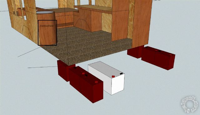
To be honest you lost me with a lot of what you were discussing!
I understand what you are saying about hooking all of the batteries up for cranking since the load is then split between 7-8 batteries instead of 1.
As far as the charging current being much more than it should, thats why I was trying to pick an alternator that would have a limited output between the c20 and c10 rate for the bank as a whole which is between 45-90 amps. I'm assuming that on the generator I can adjust the throttle of the motor to control the output of the the 3g/6g alternator.
I'm not sure what you are talking about with the sparks. When ever I jump start a car I put the negative on first starting with the working car then the dead car, then positive to the good car then to the dead. Removal is as you described, last on first off. Is this wrong or dangerous?
The reason for separating the battery bank in half is for better weight distribution, after all I'm adding 500lbs just from the batteries let along the mounting hardware and I want to minimize it's negative impact on the vehicles handling considering the van already handles like crap compared to a car.
Hopefully you can see in the picture what I have in mind as far as layout. By symmetric I meant that all wires from each battery will be the same length, size etc. I wanted to bring all individual battery connections from the bank to the electrical panel so that down the road if I ever build a charge controller, I can easily tie each battery into the controller as opposed to having to build one at each 1/2 of the bank because the wires are all terminated near the batteries.
I've considered relays but don't they draw electricity to activate them and hold them active? If I understand correctly, the bigger the relay, the more electricity it uses to stay activated.
At some point I would like to have a digital display that can read the batteries voltage, either one for each battery or one that is hooked to all and a switch to control which battery it will display.
I was going to run a single LED from each battery to the electrical panel, arranged to show their corresponding batteries position on the van so it is easy to visually tell if each battery is connected to the bank. This is so that I do not have to crawl under the van to check each batteries fuse if there is a problem.
The 15' is needed to get from the driver side 1/2 of the bank to the electrical panel, this also accounts for slack to do terminations and for raising and lowering the battery from under the van. I was considering putting the 1/2 bank blocks at the 1/2 bank location instead of the electrical panel, then I could run 2 1/0 cables from each 1/2 bank as opposed to 6 4ga cables from each 1/2 bank.
The plan is to always have the banks at least split in half, only the connections between the halves would be rearranged but if I understood you correctly, it is ideal to isolate batteries that are in a parallel connection.
As for the wiring, 15' of 4ga at 50 amps will drop about .18v to the 1/2 bank blocks. All connections from the 1/2 bank blocks would be in the electrical panel so their voltage drop should be much smaller than anywhere else especially since those connections will be made with 1/0. Really I was hoping to use 8 ga to the 1/2 bank blocks since their voltage drop at regular power levels won't be too much, actually 20 amps on 8 ga is about the same voltage drop as the 4ga at 50 amps. 20 amps from each battery when run at 12v is 120a/1440watts. Realistically I expect the average current draw to be about 5a per battery which equates to about 360 watts. At that power level with 8ga wire, the voltage drop is about .047v, with 4ga it's about .018v.
I'm also trying to keep the cost down where I can.
I'll look into relays but don't they drop a significant amount of voltage along with their energy usage to keep them activated? The only thing I can think of that doesn't use electricity would be switches.
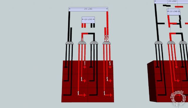
Anyway, this is how I was planning on hooking up the batteries. I need to go look up info on how the starter relay works. I'm still confused if I have to worry about damaging anything hooked up to power when I disconnect the 6 trojan batteries and then reconnect them after welding or when starting the van with all the batteries hooked up.
Posted By: oldspark
Date Posted: March 11, 2012 at 8:37 AM
/end PS.
It beats me why people want deep cycle or marine batteries for cranking.
Your search for a limited alternator output is pointless - it doesn't work that way. Current limiting (if used) is required on each battery.
Yes, your jumper battery connection method is wrong - even based on conventional rules.
The simple rule for all (-ve chassis) battery connections is that WHENEVER dealing with the +ve connections, the -ve shall be disconnected - ie, -ve is off first, on last.
Relay power usage should be insignificant - usually under 250mA but more for large relays (perhaps 1A to 2A for your PAC etc).
But they are only used when the vehicle is charging or when the batteries are required, and I'd hope that their added load is negligible compared to the alternator output (and what the batteries will need to recharge). Your welder and battery capacity also make the relays insignificant when in use (though arguably your main battery should be supplying the relays). Some batteries have a self discharge current greater than what a relay uses.
But relays are essentially a convenient remote heavy-duty switch to overcome long cable lengths or negate your need to move.
But the alternative is manual connection or switches, or leaving connected and risking battery life etc.
Maybe I should have used the phrase "same path resistances" instead of symmetrical or balanced. They were not intended to mean mirror images or weight distribution.
They are not equal paths as depicted in your diagrams. You'd have to use extra fat gauge (extra cost!) to achieve that.
Did you search the web for inter-connection examples?
However, I did describe the cheaper and probably more sensible two lots of 3 in parallel arrangement.
I think you should reread my post (and my previous replies) until they gel.
I am repeating the same basic stuff, sometimes merely paraphrased or adapted as your installation detail increases.
Otherwise there are references that may express better than I.
The volmeter and LEDs should be easy (eg, 6 thin wires).
Posted By: meltmanbob
Date Posted: March 21, 2012 at 8:17 PM
Regarding the cabling being symmetrical, I meant resistance by using the same length of cabling and gauge regardless of physical location.
I talked to a few RV places here and one confirmed that they have used multiple relays in parallel instead of a larger one. I know that there is what is ideal but then there is reality for me in terms of what I have to spend. I have tons of the square and rectangular Ford relays, 30/40 and 20a respectively. The Highest current draw will be when welding which I don't expect more than 50 amps through each battery (3 batteries per bank, 2 banks in series, 150a welding current). The plan now is to use at least 4 of the 30/40a relays per battery so that each one is operating away from it's limit and so that multiple relay failures will not make the system fail. A single relay should be more than sufficient for normal loads considering when run as a 12v bank I will have twice the capacity which cuts the current draw in half.
I'm not sure how I want to have everything triggered to be somewhat automated but I'll figure that part out. I will either use a push button or a latching relay to control the disconnecting relays so no electricity is wasted unnecessarily.
I was thinking about the consequences of having both the vehicle alternator and the generator hooked up and powering at the same time. This seems very similar to when you jump a car, there are 2 complete electrical systems tied together. From my understanding most of the potential damage caused to equipment hooked up is from making and breaking connections while there is a load which is why for welding, I'll isolate the loads from the bank first and then rearrange the bank for 24v.
So as it stands, equal path resistance, individual disconnects for each battery, individual fuses for each battery. I'm going to work on a circuit diagram as soon as I finish figuring out what triggers etc I want to control the system.
On a side note, I'm considering replacing the stock alternator in the van with a Ford 3G just like I have for the generator and my mustang. I figure the redundancy will be good in the event that I have one die.
Posted By: oldspark
Date Posted: March 22, 2012 at 2:13 AM
With fuses for each relay?
For (legislated) AC stuff, that takes special approval. It requires matched contacts and cable resistances to ensure current sharing.
And then if one fails or switches slower so the others take the brunt...
Admittedly the example I am thinking of involved using 3 breakers instead of one for physical reasons. But they were breakers (contactors) so that if overloaded, they would trip off.
Your equivalent is to have each relay fused, though I'd suggest (self-resetting) circuit breakers because short duration high currents are not uncommon when connecting batteries. (And whilst relay contacts and cables may handle it, normal fuses won't.)
There can also be a contact issue if relying on NC contacts. They do not have the electro-magnetic force that keeps them together - merely the spring force. (Hence why NC contacts generally have a lower current rating than NO contacts.)
Multiple relays may also consume more power than their larger counterparts.
I sense a false economy here, but you can suck it and see...
At least using relays between the paralleled batteries negates the need for those long runs to your central switchbox, it should only be one cable for each polarity per bank - ie, 4 cables. (Arguably 3 if one bank is locally grounded.)
But then the series/parallel switching relays can be local too - no need for those 4 cables either...
I'm not sure how using a latching control relay will save much power. Using latching relays for all makes sense, but then there is their cost. (Though I was able to buy 80A SPST latchers for ~AUD$5.)
But I assumed that compared to the load currents, the relay power would be negligible. And the same when charging.
If the load is low, take it from a single battery.
And keep in mind that equal paths is more than equal cabling - it's how they are interconnected. That link I provided compares the cases of 2 and 4 batteries in parallel.
Posted By: two12
Date Posted: April 02, 2012 at 12:48 AM
I have a smaller set up that includes 3 AGMs for a total of 360ah but each is isolated.
the only thing I can add that may be of some help here is that I would add at least one solar panel and reputable charge controller just for the sake of battery health/fitness. the modern solar charge controllers are way beyond any other method of charging.
I have 350watts on the roof mounted beteen and just bellow a four yakima brand roof racks, they are mounted in such a way as I can still utilize the roof racks.
I also use a Honda 2000 generator for back up but it is not mounted anywhere just portable.
the problem with trying to actually rely on solar panels is they have to be in the sun so the van will get hot inside in the summer if you have to park it in full sun.
but it will really help your batteries to get at least 100watts worth of PV and a decent PVM solar charge controller just to keep them in tip top shape.
the is also a pretty good AC to DC automotive charger out now too that comes close to solar charging capabilities, it is the black & decker "VEC1093DBD" this combined with a decent inverter/generator (pure sine wave) is the best set-up I have found.
for battery status the Victron BMV 601 series monitors are the only thing I have found to be reliable. it monitors amp in/out and keeps track.
this monitor also logs data and so will the decent solar charge controllers so you will know exactly how the batteries are doing any time.
a homade generator might be oK for bulk charging but be sure to finsih that off with something else.
good luck with the van and keep us posted!
Posted By: oldspark
Date Posted: April 02, 2012 at 5:40 AM
two12] wrote:
he modern solar charge controllers are way beyond any other method of charging.
I'm curious how you justify that.
PS - meltmanbob is aiming for cheapness. Solar was an OP suggestion, albeit to power rather than trickle & float charge.
And I'm glad you too isolate your batteries. Too many learn the hard way!
Posted By: two12
Date Posted: April 02, 2012 at 8:44 PM
oldspark wrote:
two12] wrote:
he modern solar charge controllers are way beyond any other method of charging.
I'm curious how you justify that.
from what I have found the solar charge controllers have way more sophisticated/advanced charging algorithms.
they also keep a float charge going as long as they have sunlight.
many are programable and you can input the specs exact from the battery manufacturers.
there are also true deep cycle batteries specifically designed for solar intsallations but these are not recomended for mobil aplications.
hey Oldspice, while I have your attention, I could really use your expertise again on this topic: https://www.the12volt.com/installbay/forum_posts.asp~TID~131100~get~last#655101
thanks
Posted By: oldspark
Date Posted: April 02, 2012 at 10:16 PM
But normal "intelligent" chargers should have the same capabilities, and do not suffer from the solar situation of insufficient charge current AT LEAST once per day (ie, at night & whenever insufficient solar panel output).
I think normal intelligent chargers still lead the technology and solar follows. Solar merely change the chargers front-end (panels, MPPT etc).
And though multiple charger re-connections itself is questionable, if the charger were always to initially connect in bulk mode (not float mode). I'm sure that would be considered detrimental. (Not all chargers have a "memory" that continue their mode after a power outage.)
FYI - Solar, though expensive, can be good as an "unpowered" trickle charger. But batteries for high power applications like this thread are very expensive and inefficient (and anti-green) as it is, adding copious solar probably makes that far worse.
As to deep cycle batteries, I like what I read this morning at otherpower.com - namely that there are no "deep cycle" (lead-acid) batteries, merely batteries that withstand deep cycling better. And they too say NEVER lower than 50% but preferably under 20% discharge.
[That otherpower link is to their battery comparison page despite their totally wrong specs on the D7 battery (probably obtained during older political propaganda days).]
Posted By: oldspark
Date Posted: April 04, 2012 at 8:18 PM
Note the lower voltage for ~11.9V for 0% capacity - ie, a 0.8V difference between 100% & 0%.
I mention that because I usually write of my simple "10% per 0.1V" ROT as being conservative, but that is based on a ~1.2V range - ie, 12.67V to ~11.5V (wet cells).
(And I think I mentioned that ROT in this thread.)
Note too what OtherPower say about not discharging more than 20% and never more than 50% without recharging. And that discharging 75%-80% WILL cause damage even if deep-cycle batteries.
[ I don't disagree, but essentially all discharges damage to some extent (except as required for "exercise", and noting small discharges are negligible or normal), but that's a complex area and very dependent on factors like how soon they are recharged etc. ]