external power supply on conversion van
Printed From: the12volt.comForum Name: General Discussion
Forum Discription: General Mobile Electronics Questions and Answers
URL: https://www.the12volt.com/installbay/forum_posts.asp?tid=128787
Printed Date: May 13, 2026 at 2:55 AM
Topic: external power supply on conversion van
Posted By: wimperdink
Subject: external power supply on conversion van
Date Posted: October 09, 2011 at 11:46 PM
I am considering adding some additional power supplies to my 1993 GMC Vandura 2500 Conversion Van by Explorer. I occasionally use the van for camping on longer road trips. I would like to be able to power a few things without having to run the engine to keep power up for the accessories while camping.
My intended install is to use a through hull marine 20 amp plug to bring the 110 ac 20amp power in. Attached to this plug will be a standard power strip with the gfi breaker built in. This power strip will operate the heater, digital converter tv box, tablet pc charger, and the power supply.
The 12v power supply will be a 350w computer power supply rewired to use the clean 12.6v dc outputs to power the vans accessories without needing to run the engine; ie the stereo, tv, 6-pack cooler, phone charger etc.
I've run a small camper with one of these in the past using relays to disconnect the 12v battery when the 110 cord was powered up.
The question I have is how should I tie the power supply into the van's 12v system. I am wondering if I can just tie the 12v from the power supply into the vehicles battery and use a standard 40a auto spdt relay to disconnect the power supply from the vans system by the ignition circuit, and will the steady 12.6v output from the power supply hurt the van's battery tying in like this? Do I need to use blocking diodes between the two?
Thanks for any advice. :)
Replies:
Posted By: oldspark
Date Posted: October 10, 2011 at 1:10 AM
You can't use a PC PSU to connect to a battery - you must use a battery charger (a 12V car battery system is not 12V whereas a PC PSU is; and chargers are typically up to 14.4V).
Disconnect the battery if using the PC PSU, not diodes.
Disconnect the battery if using the PC PSU, not diodes.
Posted By: wimperdink
Date Posted: October 10, 2011 at 1:25 AM
I appreciate the quick answer... and just another quick question based on your answer. Is there a relay that would be of a high enough amperage that I could use to disconnect the battery when I power up the power supply or would I have to use one of those manual auto parts store disconnects? I would like to put in as many fail safes as possible in case someone other than myself is using it.
When I set up my small camper, I just had normal 14 gauge wiring to deal with as it was only running 3 1156 bulbs and a car stereo so I was able to use relays to disco the battery when the power supply turned on.
I'm also going to see if I can separate the conversion accessories bus so that it would be simpler to use a relay to separate the systems when on shore power. I appreciate any suggestions you may have. :)
Posted By: oldspark
Date Posted: October 10, 2011 at 2:06 AM
Relay size is not a problem, it's more a case of how?
A relay that disconnects the battery (NC contacts) which - if it fails - reconnects the battey.
Or a relay of any type between the battery and vehicle which - if it bounces or fails - could be a hazard.
Or a change-over relay selecting battery or PC PSU which ditto - may compromise driving safety.
Best is an interlocked mechanical switch, or simply mechanical.
You could leave the starter motor (heavy) connected to the battery (that saves a few hundred Amps of switch/relay rating).
Many people use battery chargers which suits vehicle electrics (13.8-14.4V) and recharges or floats the main battery.
Why not boost the PSU output to 13.8V, that might solve all the problems?
It may be able to be left connected when not being used, else a (~400W/12V 33.3A=) ~30A or larger relay that connects it when being used.
Many convert PC PSUs to other voltages.
But boosting from 12V to ~13.8V may be as simple as adding 3 series diodes to its sense/feedback from the 12V output. (IE - 3x 0.6 - 0.7 diode drops = 1.8 to 2.1V.) That voltage subtracted thru the 12V output sense loop means the PSU will boost output by 1.8 - 2.1V => 13.8 - 14.1V.
Purrrrfect! (Depending on battery, but normal range is 13.8-14.4V.)
That also means you have your battery to supply the voltage sags when your audio hits those big thumps... oops sorry, wrong OP....
But that rectifier (aka charger) and battery is a UPS - an Uninterruptible Power Supply/System (not all UPS are AC output!).
If your PC PSU blows, you can get to it without tripping over things in the dark....
Mind you, you might want an alarm followed by a timed relay else battery protector to disconnect the battery is the PSU fails, or a dual-battery, etc etc...
Are you game for some PSU hacking?
Why not - they usually only cost ~$10 or less.
Just ensure they are disconnected from the AC supply (as in cable pulled out - don't trust switches), and that the internal capacitors are discharged (they can be over 200A DC - more than enough to maim and kill!!).
Posted By: wimperdink
Date Posted: October 10, 2011 at 4:25 PM
I am all about messing with the PSU's... I used to be a 12v installer though installing and modifications are 2 diff things. The camper I install the 300w supply to was as simple as throwing the green sense wire to ground to get the supply to power up. In that case I dedicated a couple of the 12.6v wires to diff lights and bulked the rest together to a bus for future needs. I think I had estimated around 20 amps from that which is more than enough for my needs.
The only reason I wanted to use a 350w is because I already have 3 of them in my garage. :) I had not heard of boosting the voltage and I will be rereading your posts until I understand it fully. I appreciate your help.
The only reason I wanted to use a 350w is because I already have 3 of them in my garage. :) I had not heard of boosting the voltage and I will be rereading your posts until I understand it fully. I appreciate your help.
Posted By: oldspark
Date Posted: October 10, 2011 at 5:42 PM
Yeah - sorry, the PSU boosting was a lat minute thought... (Obvious in retrospect.)
As to PC & ATX PSUs etc - what cheaper is there?
A few years back I went though the exercise of finding a suitable 12V supply for a water system (my "sump pump" which sat in gully-traps to pump waste water onto the garden etc during drought - a $20 marine pump, an SPST relay and 2 (brake fluid) level switches - all under $30).
Even 12V 2A supplies were >$30, and I think I needed 3A.
Then the obvious struck - a surplus PC PSU - often available for $5 - $10. Way more than 5A @ 12V & 20A @ 5V in a well grounded/earthed case complete with "remote" power up option.
That can be housed indoors for easy power-off or on as needed, and maybe controlled by the pumps/switches too (not that I've considered that yet).
Anyhow, many modify for other voltages - usually boosting the high current 5V rail to 12V (13.8V etc) for audio amplifiers etc. It has been done/mentioned over at mp3car.com and elsewhere.
In SMPS, voltage boosting is easy (unlike linear/transformer PSUs).
Rating-wise, current is current, and voltage is merely insulation (unless there is overvoltage or spike protection like Zenors or MOVs etc).
And despite whatever circuit complexity for the SMPS, they all usually depend on a single sample/feedback line from the output for regulation purposes.
Find that feedback - usually it's a resistive voltage divider - and insert a few diodes or whatever gives the required drop.
Knowing the SMPS (dc-dc converter) chip helps heap - then you know which pin is the feedback and can trace the circuit form there.
The are typically 8 or 14 pin DIP IC packages. (MC33363, MC34063, TL496, etc.)
Of course some manufacturers disguise their chips, but it's usually easy for figure out.
Of course I cannot stress the safety issues enough.
Not only the AC side, but SMPS usually involve HVDC - ie, >1.4 times RMS, hence over 170VDC & 325VDC for 120 & 230 VAC respectively).
And if you are a 12V installer, you may be aware that HVDC occurs at a voltage far lower than HVAC - ie, 80VDC is far more dangerous than 120VAC etc.
[ Just last night I forwarded a youtube link with an Indian electrocution (on top of an electric train). Though the title claims "40,000V", I suspect it's the standard 500VDC to 1500VDC train supply. I like the way the, er... person "petrifies" and....
You may survive 220VAC and 220,000VAC shocks, but not DC! ]
Posted By: wimperdink
Date Posted: October 10, 2011 at 7:19 PM
I should probably advise of my level of understanding lol. I know what a blocking diode does and what a resister does... I can only use them in the simplest forms like lowering voltage to operate a light emitting diode etc. I've used relays a bunch for changing + to - (ie door locks) and using them as a switching solenoid to use a smaller switch on a higher amp circuit. I used to install alarms, gps trackers, vehicle monitoring type stuff and a myriad of other accessories. Actually working with board level circuitry is greek to me. I can usually follow a diy instruction or read a basic schematic. I can tell your level of understanding far exceeds mine so the following quote left me drooling.
Now that being said I'm going to ask a noob question lol. If the accessories in my vehicle are designed to operate within a given range of 12v, why would the 12.6 volts not suffice with enough amperage? I realize an alternator pumps out up to 14.5v at a certain rpm which keeps the battery charged with a load on it, but wouldn't the 12.6v from the psu maintain low load accessories without draining the battery? I would understand if I was running high power amps and a high wattage head unit but I've got a simple 200w head unit that would never be turned up loud while not traveling. The cooler and the 12" tv would be the highest draw and I havent checked what they use. The tv turns itself off if the battery voltage drops below 10.5v and the cooler I'm not sure. It has run 3 or 4 hours (i forgot to unplug it) without running the battery out so it can't be too high of a draw. I know if I can separate the conversion accessories that the psu will offer plenty of power to operate them, I was just concerned about what kind of damage I would do the vans systems if any.
oldspark wrote:
Knowing the SMPS (dc-dc converter) chip helps heap - then you know which pin is the feedback and can trace the circuit form there.
The are typically 8 or 14 pin DIP IC packages. (MC33363, MC34063, TL496, etc.)
Of course some manufacturers disguise their chips, but it's usually easy for figure out.
Now that being said I'm going to ask a noob question lol. If the accessories in my vehicle are designed to operate within a given range of 12v, why would the 12.6 volts not suffice with enough amperage? I realize an alternator pumps out up to 14.5v at a certain rpm which keeps the battery charged with a load on it, but wouldn't the 12.6v from the psu maintain low load accessories without draining the battery? I would understand if I was running high power amps and a high wattage head unit but I've got a simple 200w head unit that would never be turned up loud while not traveling. The cooler and the 12" tv would be the highest draw and I havent checked what they use. The tv turns itself off if the battery voltage drops below 10.5v and the cooler I'm not sure. It has run 3 or 4 hours (i forgot to unplug it) without running the battery out so it can't be too high of a draw. I know if I can separate the conversion accessories that the psu will offer plenty of power to operate them, I was just concerned about what kind of damage I would do the vans systems if any.
Posted By: wimperdink
Date Posted: October 10, 2011 at 7:21 PM
Oh forgot to add that I've been burned a time or two with low amperage DC. Its ugly lol. 110a/c sucks, 240ac will throw ya across the room but even low voltage high amp dc can cook ya.
Posted By: oldspark
Date Posted: October 10, 2011 at 8:50 PM
If your PSU is 12.6V, it may be ok, but 12.6 seems a bit high - they are supposed to be 12.0V with (as I recall) a 5% tolerance, though maybe it is 10%.
First, some "benchmarks" or theory:
A (rested) 12V battery varies from maybe 11.4V (flat) to 12.7V (fully charged).
A battery taken off a charger will have a "surface charge" that can take it to ~13.6V (even if it is flat).
Surface charge can take many minutes of full beams (>100W) to dissipate - ie, there is lots of "charge" in that surface charge. Normally surface charge dissipates itself within 24 hours.
Chargers (aka rectifiers, alternators etc) are set for ~13.8 to 14.4V to "adequately" charge 12V batteries.
ERGO:
A 12V system is rarely 12V.
You cannot determine a battery's SOC (state of charge - ie, %age of full capacity) whilst charging or after charging (ie, battery/charger may be 14.4V and the battery might measure 13.2V if the charger is removed, but the "actual" battery may be 12.3V (~50% discharged).
Why not a 12V or 12.6V PSU?
If the PSU is 12.6V and the battery is 12.7V, will the battery discharge into the PSU? (Ditto for alternator at 13.8V etc.)
Will a battery blow the PSU anyhow? (IE - a PC PSU was never designed to connect to a battery, therefore it may not have protection diodes etc unlike battery chargers. However that protection may not be required...)
Even if ok, the nominal battery fully-charge voltage is 12.67V (but in practice this varies) hence at least some discharge before the 12.6V PSU takes over. Partial discharge causes sulphates to form (sulfation), hence better to disconnect the battery and leave as fully charged as possible.
As to finding those chips, it's just a case (ha!) of removing the PSU cover and searching. You seem well qualified (ie, understand kicks, and can access a crew driver).
Normally PSUs are constructed quite well and only a few Philips-head screws need be removed. Then search for the chips which involves the mandatory slicing of hands and fingers on sharp edges as you manipulate cables out of the way etc.
Some chips will merely be 4 or 6 pin opto-couplers, and others may be on fan control or temp-sensing boards. The SMPS chips are normally in with the big chokes (coils) and capacitors, though the chips will dive FETs which "buffer" the coil switching.
What brands and models are your PSUs? You may be able to find pics or conversions on the web.
Posted By: wimperdink
Date Posted: October 10, 2011 at 9:53 PM
Ok I see the issue with a back feed of a battery that is charged at a voltage higher than what is being put out by the psu. the 12.6 volts was what I measured on the 300w that I did a couple of years ago. I haven't converted anymore but am going to do so tonight just for the fun of it and get this project rolling.
So a blocking diode wouldn't correct the issue of back feed? I learned what I know on the internet and read a lot using the fluid method... the blocking diodes I always pictured as a one way valve... it would let current flow one way but not back into the device. Thats why I suggested that. I see your point though. I need to get a couple of psu's modified tonight so I can see what realtime output is on them. I do have a conversion bus up under the hood that runs a short 10guage wire direct to the battery. I need to find out what all it controls as it would be easy to disco what I need from the battery using relays and just run that stuff off the psu. I'll post my findings soon.
So a blocking diode wouldn't correct the issue of back feed? I learned what I know on the internet and read a lot using the fluid method... the blocking diodes I always pictured as a one way valve... it would let current flow one way but not back into the device. Thats why I suggested that. I see your point though. I need to get a couple of psu's modified tonight so I can see what realtime output is on them. I do have a conversion bus up under the hood that runs a short 10guage wire direct to the battery. I need to find out what all it controls as it would be easy to disco what I need from the battery using relays and just run that stuff off the psu. I'll post my findings soon.
Posted By: oldspark
Date Posted: October 10, 2011 at 10:12 PM
Blocking diode yes, BUT....
You have that diode permanently between the battery and the load?
If so, a BIG diode for all loads, else a still big diode if those loads are separate from the other battery connected electricals.
Then a diode for the PSU.
The diodes have probably at least a 0.7V drop across them - maybe more.
But even if as low as 0.3V for a low-current Shottky diode - the loads get 12.3V instead of 12.6. The battery must be diode connected so it still discharges to 12.6V (ie, 12.6V less 0.3 diode = PSU 12.6 less 0.3V etc). (Maybe a higher voltage diode for the battery to prevent its discharge?)
But the problem may still be high-current diodes - eg, >30A in your case, therefore 0.3 or 1.0V x 30A = 100W or 300W of heat.
The solution to high-current isolation diodes is relays - at least wrt these situations. (PSU & battery isolation etc. Even diode battery isolators have been shunned for ages - they use voltage or charge sensing relays etc.)
Lots of ways...
If your alternator is charging, that disconnects the NC contacts that allow your AC PSU (eg, see the UIBI battery isolator).
Or AC connection with PSU output disconnects battery etc.
And I feel my oft recommendation... a voltmeter; maybe 2.
One for the PSU. One for the battery. Both 3-digit displays.
Usually quite cheap off eBay. (I have a smallish blue-LED meter I integrated into my dash, and others including larger back-lit LCDs - all ~$10 or less from Hong Kong etc; usually well under 10mA current drain (7mA for LED & backlights; less for non-lit LCD).
Posted By: wimperdink
Date Posted: October 10, 2011 at 10:39 PM
lol your sparking interests in me that I haven't played with in ages. I just went out and tore apart 2 psu's and temporarily grounded the sense wires just to see what voltage they were pushing. I remember my 350 was pushing 12.6 on the camper. That was the first one I ever did. tonight I did two of them.
200w psu was pushing 11.57v
300w psu was pushing 11.86v
I'm not sure how the first one got that high. So now I'm liking your original thought on boosting the voltage output on these. I did read another page on it. I still don't fully understand what he was doing because he didn't explain it like I'm 5. lol What I read I think I understand that he just created a load on the 5.5v wires by throwing a couple of resistors in series. As he mentioned this will generate heat and will require a heatsink to dissipate it. Is this basically what you were suggesting earlier in this thread?
I do understand now what you mean about blocking diodes and I didn't think that through well enough to start with. I forget I was working with low power consumption devices when I did this stuff more.
Posted By: oldspark
Date Posted: October 11, 2011 at 1:45 AM
Hmmm - interesting read... Or not?
As I understand it, he increases the voltage of the 12V by placing a the 10A load on the 5V rail (2 x 1R (ohm) resistors; V=IR hence I=V/R = 5V/1Ohm = 5A per resistor).
That I suggest only occurs in that instance due to its (poor) design.
There is a voltage drop along the shared +12V & +5V ground due to the 5V 10A load so the 12V ups it voltage to compensate.
That's what I'm suggesting, but instead of 10A and 50W and a bluddy hot resistor, and unpredictable outcomes (depending in track resistance, the load, and the design), I suggest a voltage drop of (eg) 0.6V or 1.2V or 1.8V etc at micro-Amps by using diodes.
(A well designed PSU would not have one rail effect the voltage of another.)
Two things I like about that link however:
1 - his hover-over color coding (I thought yellow was 12V!)
2 - the next pic (no copyright notices noted)
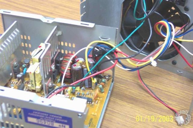
... where the chip (IC) on the mid-RHS (partly obscured by the case) might be the SMPS chip we are looking for. (It's the black "beetle" with 2 of its 14 legs visible.)
And that one still has its numbers!
But it might be another chip elsewhere...
So, can you see the chips in yours? And post the numbers? (probably starting with letters like MC, ICL, T etc; the "lowest" numbers are usually date codes....)
As to your 11.57, 11.86 & 12.6V outputs - yep, that's a typical range.
The 5V definitely has to be within +/-10% (4.5V to 5.5V) because more or less can damage traditional logic chips (TTL etc).
12V is often for fans and motors (disks) which are not that critical.
But you see the range - and you want to convert from (say) 11.5V to 13V - 14V. That's a 1.5V to 2.5V increase. If that's resistive, it'll get hotter than the diodes (ie, 1.5V @ 20A = 30W etc).
So we find the feedback "loop", splice in a few diodes (can add a switch to short some of them out to drop the voltage) and you set or dial whatever voltage you want. (Well, in 0.6V steps unless you use Schottky diodes or other tricks.)
As I understand it, he increases the voltage of the 12V by placing a the 10A load on the 5V rail (2 x 1R (ohm) resistors; V=IR hence I=V/R = 5V/1Ohm = 5A per resistor).
That I suggest only occurs in that instance due to its (poor) design.
There is a voltage drop along the shared +12V & +5V ground due to the 5V 10A load so the 12V ups it voltage to compensate.
That's what I'm suggesting, but instead of 10A and 50W and a bluddy hot resistor, and unpredictable outcomes (depending in track resistance, the load, and the design), I suggest a voltage drop of (eg) 0.6V or 1.2V or 1.8V etc at micro-Amps by using diodes.
(A well designed PSU would not have one rail effect the voltage of another.)
Two things I like about that link however:
1 - his hover-over color coding (I thought yellow was 12V!)
2 - the next pic (no copyright notices noted)
... where the chip (IC) on the mid-RHS (partly obscured by the case) might be the SMPS chip we are looking for. (It's the black "beetle" with 2 of its 14 legs visible.)
And that one still has its numbers!
But it might be another chip elsewhere...
So, can you see the chips in yours? And post the numbers? (probably starting with letters like MC, ICL, T etc; the "lowest" numbers are usually date codes....)
As to your 11.57, 11.86 & 12.6V outputs - yep, that's a typical range.
The 5V definitely has to be within +/-10% (4.5V to 5.5V) because more or less can damage traditional logic chips (TTL etc).
12V is often for fans and motors (disks) which are not that critical.
But you see the range - and you want to convert from (say) 11.5V to 13V - 14V. That's a 1.5V to 2.5V increase. If that's resistive, it'll get hotter than the diodes (ie, 1.5V @ 20A = 30W etc).
So we find the feedback "loop", splice in a few diodes (can add a switch to short some of them out to drop the voltage) and you set or dial whatever voltage you want. (Well, in 0.6V steps unless you use Schottky diodes or other tricks.)
Posted By: wimperdink
Date Posted: October 11, 2011 at 2:16 AM
I'm taking on an education here. As is always with me I have to try things to understand. Since I didn't have the required resistors, I opted for an 1157 automotive light bulb. I threw the red 5v line to the bright side of the bulb (not knowing the resistive qualities) and it boosted the 12v line from 11.87v to 12.06v. (cool didn't see that coming) Now that didn't solve the issue, but it gave me a good understanding of what your suggesting. :)
The numbers on the 14 leg chip are...
top row = 45D3TVM
bottom row = TPS3514N
The numbers on the 14 leg chip are...
top row = 45D3TVM
bottom row = TPS3514N
Posted By: oldspark
Date Posted: October 11, 2011 at 2:32 AM
Looking for a suitable circuit example, I found this page: electronic-circuits.blogfa dc-to-dc-converter.
Although I wanted to use one of my aforementioned MC34063 figs from that page, I'll use the "LM2577 5V to 12V DC Converter step up Voltage Regulator" instead... (about 3/4 down the page)
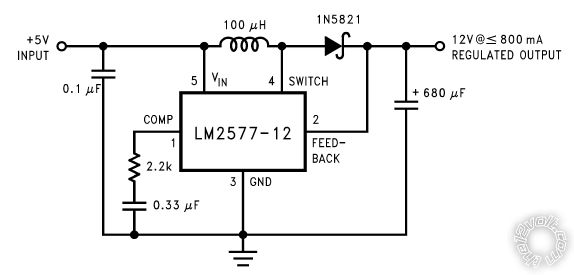
Think of the LM2577 as being your entire PSU for 12V except for a few components - like the 100uH coil (transformer) and the 0.1uF & 680uF input & output filter capacitors and a diode and RC crap (2.2k & 0.33uF).
It has 5V input which it converts to 12V (using magic and that transformer - aka coil or choke).
How does it know it is outputting 12V? It has a FEEDBACK or SENSE terminal (#2). If the output drops, pin #2 drops and the "magic box" increases output voltage etc. That's called regulation.
What happens if we insert a diode between the output and pin #2? Assuming the correct orientation (ie, the diode's arrow head points from the Output to #2 which means the diode's LINE-end is towards pin #2), then there is a 0.6V drop.
So output is 12V, pin #2 is 12V - 0.6V - 11.4V which is not its programmed 12V so it bumps the output 0.6V. (Hence #2 = out = 12.6 less diode 0.6V = 12.0V so all is cool.)
Same for 3 x 0.7V diodes = 2.1V => output is (12V + 2.1V =) 14.1V.
Too easy eh?
Look at most of the diagrams on that link.
Almost all have a FB = Feedback = S = Sense terminal.
Some are not direct like the LM2577-12 above - they go through a resistive voltage divider (2 resistors with or without a trim-pot (variable resistor)) so that the output voltage can be adjusted. (The LM2577-12 is a fixed 12V output, but we can trick it to go higher as I described - just as we can trick most car alternators to increase their output voltage.)
Not that the voltage divider crap matters. All we have to do is insert diodes between the actual output and the "top" of the feedback link.
However, if we find the feedback resistors, we could instead add a trim-pot so you can fully adjust the output voltage.
Maybe the PSU even has a trimpot that has been locked in place with nail-polish etc!
If the 5V rail is similar, we can boost that too. (Main danger there is its output filter capacitors that are likely to be 5V or 10V rating - not the 16V or 25V required for 12-14V etc.)
Are you getting a slightly warn feeling? If it's a short-circuit warmth, that's ok. This is a lot in one go.
But hopefully you might see that most of those diagrams are all the same as the "simple" one above - an input and output voltage either side of a coil/inductor, and some box etc that somehow controls that "coil converter". Oh - and the voltage feedback. The rest doesn't matter - they only add that to prevent simpletons like us thinking we understand them. (At least for now...)
Although I wanted to use one of my aforementioned MC34063 figs from that page, I'll use the "LM2577 5V to 12V DC Converter step up Voltage Regulator" instead... (about 3/4 down the page)
Think of the LM2577 as being your entire PSU for 12V except for a few components - like the 100uH coil (transformer) and the 0.1uF & 680uF input & output filter capacitors and a diode and RC crap (2.2k & 0.33uF).
It has 5V input which it converts to 12V (using magic and that transformer - aka coil or choke).
How does it know it is outputting 12V? It has a FEEDBACK or SENSE terminal (#2). If the output drops, pin #2 drops and the "magic box" increases output voltage etc. That's called regulation.
What happens if we insert a diode between the output and pin #2? Assuming the correct orientation (ie, the diode's arrow head points from the Output to #2 which means the diode's LINE-end is towards pin #2), then there is a 0.6V drop.
So output is 12V, pin #2 is 12V - 0.6V - 11.4V which is not its programmed 12V so it bumps the output 0.6V. (Hence #2 = out = 12.6 less diode 0.6V = 12.0V so all is cool.)
Same for 3 x 0.7V diodes = 2.1V => output is (12V + 2.1V =) 14.1V.
Too easy eh?
Look at most of the diagrams on that link.
Almost all have a FB = Feedback = S = Sense terminal.
Some are not direct like the LM2577-12 above - they go through a resistive voltage divider (2 resistors with or without a trim-pot (variable resistor)) so that the output voltage can be adjusted. (The LM2577-12 is a fixed 12V output, but we can trick it to go higher as I described - just as we can trick most car alternators to increase their output voltage.)
Not that the voltage divider crap matters. All we have to do is insert diodes between the actual output and the "top" of the feedback link.
However, if we find the feedback resistors, we could instead add a trim-pot so you can fully adjust the output voltage.
Maybe the PSU even has a trimpot that has been locked in place with nail-polish etc!
If the 5V rail is similar, we can boost that too. (Main danger there is its output filter capacitors that are likely to be 5V or 10V rating - not the 16V or 25V required for 12-14V etc.)
Are you getting a slightly warn feeling? If it's a short-circuit warmth, that's ok. This is a lot in one go.
But hopefully you might see that most of those diagrams are all the same as the "simple" one above - an input and output voltage either side of a coil/inductor, and some box etc that somehow controls that "coil converter". Oh - and the voltage feedback. The rest doesn't matter - they only add that to prevent simpletons like us thinking we understand them. (At least for now...)
Posted By: oldspark
Date Posted: October 11, 2011 at 2:40 AM
Dang - I missed your reply.
Dang#2 - TPS3514N is not the SMPS - its a voltage supervisor chip (it measures and checks for 12, 5, 3.3V etc and outputs whatever signals if correct or not).
But that's good - we may have to trick or disconnect that chip later.
So any others - maybe 8 pin chips?
Dang#2 - TPS3514N is not the SMPS - its a voltage supervisor chip (it measures and checks for 12, 5, 3.3V etc and outputs whatever signals if correct or not).
But that's good - we may have to trick or disconnect that chip later.
So any others - maybe 8 pin chips?
Posted By: wimperdink
Date Posted: October 11, 2011 at 3:02 AM
yep 2 8 leg chips
first one....
top row = gm3843
bottom row = r345
second one...
VIPer22A
first one....
top row = gm3843
bottom row = r345
second one...
VIPer22A
Posted By: oldspark
Date Posted: October 11, 2011 at 3:29 AM
BINGO!
The VIPer22A seems to be a "driver" chip, but the GM2843 is definitely a SMPS chip.
Alas the 2843 is a current-mode PWM (pulse-width modulated; the way SMPS and some LED/lamp dimers work) so there are different "feedback" modes, but its pin #2 is its "voltage feedback" input.
So can you trace tracks from #2 to the 12V or 5V output - maybe thru resistors or a variable/trim-pot?
BTW - I find that data using google, although for some reason I am not finding or downloading pdf datasheets like I used to. (Probably some config problem since my "still recovering" rebuild.)
In fact at the moment my text entry has gone haywire (double line feeds etc), so maybe a good time to reboot. And prepare for an appointment tomorrow (not that I ever get distracted!)
But at this rate, you are going to have to change your username pretty soon. Then again, I Am An Idiot is anything but....
And it's not like I'm old... (ha ha!).
Posted By: wimperdink
Date Posted: October 11, 2011 at 12:40 PM
You may have lost me here but I'm going to give it a try. I will be out of town for a couple of weeks so this project will have to be back burnered until I return. :( This will give me time to read and learn and understand. :) I might take it with me along with my tools for something to do in my off time.
Posted By: wimperdink
Date Posted: October 11, 2011 at 3:35 PM
Well a lil more poking and prodding produced the answer to my design. I don't need to hit much more than 12v to operate everything as long as the amperage to the PSU is high enough. I took a gander at the fuse block for the conversion package last night. There are two blocks one is powered through a relay on the ignition wire to fire only when the key is on,(tv, cb, digital tv box, rear radio) and one block is direct to the battery to operate interior lights etc. Everything I want to power is attached to these blocks save the car stereo. There are extra positions on both blocks so realistically I can take the car radio off the van's oem fuse block and wire it instead to the conversion bus. Then through the use of regular automotive relays, disconnect the conversion bus from the oem system essentially disconnecting from the vehicles battery when the psu fires up.
That being said, I am still interested in following through on boosting the psu's output just for the knowledge and fun of it. There's more than one way to skin a cat and I'm fond of a challenge even at the risk of the occasional scratch.
That being said, I am still interested in following through on boosting the psu's output just for the knowledge and fun of it. There's more than one way to skin a cat and I'm fond of a challenge even at the risk of the occasional scratch.
Posted By: oldspark
Date Posted: October 11, 2011 at 9:57 PM
That sounds good - essentially "mechanical" switching using the OEM bits.
Simple, quick, and solves your issue.
Yep sure, boosting PC PSUs can come later - after all, isn't that probably the cheapest battery charger or 20A etc supply available?
The next step - identifying pin-1 on ICs/chips (ie, where the dot is), therefore finding pin-x - in this case pin-2 next to pin 1, and tracing/mapping the copper PCB tracks from pin 2...
Unless we can get a circuit diagram etc for that PSU (or a similar one).
See you when you get back.
Posted By: wimperdink
Date Posted: October 12, 2011 at 1:58 PM
Ok I was able to do a test... I manually disconnected the bus from the ignition power source and threw the 230w supply that I modified last night on. It powered up my tv/digital box/90w inverter/cb radio. I didn't try anything else. Something I found interesting is with no load the 12v side showed 11.3v... when I hooked a headlight up to it to test it last night it raised the voltage to 11.9v. Today with all the other stuff hooked to it, it went only to 11.87v which would indicate the headlight used more power than the other stuff. The thing I don't understand is why when you throw a load on the 12v wire, the output rises. Its like the PSU is compensating for the higher loads which is great but odd.
Since this smaller psu worked so well, it will become my conversion unit and I'll save the 300w for something else that has higher demands. Just too bad i don't have time to make this permanent before this road trip. :( Either way I'm happy to have it figured out. I might not even put a tv in the camper now. How can I get better than leather captain chair seating and stereo sound already built in.
Keep the fireworks down until I return. :)
Posted By: wimperdink
Date Posted: October 29, 2011 at 7:52 PM
Well I'm back and finished wiring everything up. The good news is everything works. The bad news is that the tv doesn't work well. It appears to want more voltage. I say this because the audio breaks up when running off the psu but is fine when running from the van while its running. It breaks up when on battery without the van running too. Back to the psu project. :-)