fuel gauge and sending unit
Printed From: the12volt.com
Forum Name: General Discussion
Forum Discription: General Mobile Electronics Questions and Answers
URL: https://www.the12volt.com/installbay/forum_posts.asp?tid=130935
Printed Date: May 12, 2026 at 7:43 PM
Topic: fuel gauge and sending unit
Posted By: cahilj
Subject: fuel gauge and sending unit
Date Posted: March 17, 2012 at 12:22 PM
I'm reaching out here. I've asked this same question on several forums now, and no one can seem to give me an answer.
I have a fuel level sending unit that is 12v. It provides a 0-5v output for the gauge (0 empty, 5 full). I would like to use it with a gauge that has the typical GM input of 0-90 Ohm (0empty, 90 full) at 12v.
I've spent hours searching, but I can't seem to find anyone who has done this, and I'm not even sure it's possible. I found one (yes, only one) guy who did something similar in a battery powered Porsche. The Porsche gauge is 0-75 Ohm input. Link to site- https://cruzware.com/peter/blog/?cat=6. It's about 1/3 the way down, you'll see this-
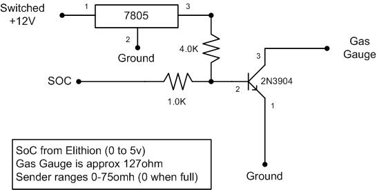
My knowledge of circuits like this isn't enough to be able to know if this would work or not. I realize the values would probably need to be changed. Can someone tell me if I'm at least headed in the right direction? And if I am, how do I go about getting the right values? Thanks.
Replies:
Posted By: KPierson
Date Posted: March 17, 2012 at 7:26 PM
Your transistor is a discreet device - not resistive. With the way your circuit is set up when SOC is 0 you will have only 1vdc going in to the base of the transistor which should be enough to turn it on at which point it will output a straight ground to your gauge. As your SOC voltage drops your base voltage will drop and eventually the transistor will just shut off and not pass current at all.
-------------
Kevin Pierson
Posted By: cahilj
Date Posted: March 18, 2012 at 4:16 PM
So... you're saying this won't work? Like I said, I don't know a whole lot about these types of things, just the basics. This is just a diagram I found online. Do you have any idea what it should look like to work?
Posted By: KPierson
Date Posted: March 19, 2012 at 5:38 AM
To make it would you need to replicate the output of the correct sending unit - meaning you need a varying resistance on the output. They make "digital" potentiometers - perhaps that would work? Will be much more difficult though then a simple transistor.
-------------
Kevin Pierson
Posted By: oldspark
Date Posted: March 19, 2012 at 12:37 PM
It's called a transconductance amplifier - ie, voltage to resistance.
FETs can be used. Chips were common too - eg LM13700, but that may need a split supply (ie, +/- 5V etc).
If it is for a normal fuel gauge, I'd suggest getting the original sender.
If it's for a BCM, why not use an offset or expanded-scale gauge instead (eg a series zener diode)? But that assumes the BCM merely uses voltage for a battery-capacity or SOC.
If it's a "true capacity" BCM, then stick to its 0-5V output.
The GM gauge should be able to be modified to sense 0-5V, though it may be a high-current meter which the 0-5V BCM output cannot drive (hence need a voltage-follower).
All meters are ammeters and use resistors to convert ranges or convert voltages to current.
Posted By: cahilj
Date Posted: March 21, 2012 at 11:12 AM
I spent some more time searching and found the transconductance amplifier. I was going to ask if it would be able to work.
I can't go back to the original sending unit. It is a swing arm type, and I now have a fuel cell with foam, so I had to switch to a capacitive tube type sender.
I would like to keep the factory gauge in the dash, but I am not opposed to converting it to work with a voltage input.
Is it possible to isolate the gauge circuit from the rest of the dash, then use only the sender to drive it? If I can find out the draw of the gauge? Or am I way off base?
Posted By: oldspark
Date Posted: March 21, 2012 at 11:44 AM
Capacitive senders are usually voltage output - I presume hence your 0-5V.
Transconductance should work, it's a matter of finding he right conversion (circuit), ie, 0-5V to 5-90 Ohm or 90-5 Ohms etc.
Posted By: cahilj
Date Posted: April 03, 2012 at 8:56 PM
Well, I was able to find a company that will make me a custom ordered sender with the 0/90Ohm range. And at a reasonable price. This will save me headache and testing, and provide a warranty.
Thanks for everyone's help!
|