alternators
Printed From: the12volt.com
Forum Name: General Discussion
Forum Discription: General Mobile Electronics Questions and Answers
URL: https://www.the12volt.com/installbay/forum_posts.asp?tid=135213
Printed Date: January 12, 2026 at 1:03 AM
Topic: alternators
Posted By: kjohnson1
Subject: alternators
Date Posted: November 04, 2013 at 8:44 PM
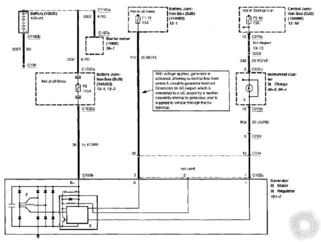
Literally after replacing the 6G alternator in my wife's Escape V6....5 times in the past 2 months (three from AZ one from Oreilly's and finally one from a USA based remanufacturer; I decided I'd had enough. Long story short: All wiring verified OK, Battery ok, Battery cables ok.
fix: 4G case with 3G internal components and regulator wire connection spliced for 3G. 100% functional and verified.
What I really want to know is how to connect some additional diodes or an additional 4-pair rectifier externally (without buying that $300 box from the Internets).
Replies:
Posted By: kjohnson1
Date Posted: November 04, 2013 at 8:51 PM
https://i1175.photobucket.com/albums/r640/bronco_5/IMG_6799_zpsa4554557.jpg
https://i1175.photobucket.com/albums/r640/bronco_5/IMG_6800_zpsa4f208d7.jpg
Posted By: oldspark
Date Posted: November 04, 2013 at 11:30 PM
I'm so glad I only use Japanese alternators. The problems I keep reading regarding these Ford (and other) alternators! And they seem nothing special - a typical non-ECU controlled alternator albeit with CAN interface for charge (light) status if I understand correctly.
And to think they seem to be modeled on a Nippon-Denso type mount (internal solid rather than outer bolt flanges).
I guess you mean the main rectifier diodes (isn't that 6?).
The (3) grounding diodes shouldn't be a problem assuming their case is NOT the Anode.
But the usually (3) anode-cased +12V side diodes are with their common heatsink electrically insulated. (Shorting their anode to GND is the same as shorting the main +12V alternator terminal to GND.)
Their best location is in the alternator where they get fan cooled. Otherwise I'd suggest a cool part of the engine bay (or in the cabin?) but maybe with a fan that cuts in when stationary (or) if over a certain temperature (compared to ambient).
I'd use a single array. I see many "dual" diode kits or addons but I get the impression they are still no guarantee and IMO overpriced, and over-rated (except electrically - pun pun). But I would consider adding a "double" or better rated array in parallel to the original internals (and then pray the internals only fail in open (circuit) mode).
It's been over 30 years since I looked at substitute stud or press-fit diodes for my alternators. Albethey mere 20A - 45A alternators, I'd find it surprising if modern rectifiers/diodes aren't available to suit modern 200A etc outputs.
And even my >40 year old alternators handled reversed battery connections (several times).
There are sites with internal circuit diagrams of 3G etc alternators.
Marry that with diode symbols - ie:
Current flows in the direction of their circuit symbol's "arrow" towards and out the "line" end - ie from right to left for --|<--.
The line end is the Cathode. I call Kathode because it looks like a K.
The symbol's line is the same as the line on a diode body, ie, current flows OUT the line end.
Hence it is easy to remember which way current flows thru a diode, and which is the Kathode or -ve end.
High current diodes usually have a metal case for heatsinking. The case can be cathode or anode.
You want Cathode cases for the GND diodes.
The same could be used for the +12V end diodes but then each case must be insulated from everything else. Most use Anode cased diodes for the +12V end so that a common heatsink can be used and then that heatsink insulated from everything other than the alternator output (usually).
If diodes are to be electrically insulated from their heatsinks, then it doesn't matter. But that would be rare in this case because it would not take much contamination or vibration to short out the electrically insulating but high heat conducting barrier - eg, mica or silicon insulating washers, or insulating heatsink compound, etc.
Posted By: kjohnson1
Date Posted: November 07, 2013 at 12:47 PM
The purpose is partially for the light. The other is communication with the PCM to determine load and therefore regulate the voltage based on that load.
The 6G alternator did come with 6 diodes, but given I've gone through more than a handful; some came with 8. As for the 3G that's now being utilized (circa 1987), it has 8....they all have 8.
Your thought on putting another array in parallel is exactly what I was thinking. I have another rectifier that I would like to enclose in a dual fan cooled container. The idea being to distribute the work and therefore life of the alternator.
Posted By: oldspark
Date Posted: November 07, 2013 at 4:00 PM
Curiosity only - where is the current sensor mounted in your vehicle? (I'd assume it is a loop type and not a shunt.)
Posted By: kjohnson1
Date Posted: November 14, 2013 at 5:36 AM
Which sensor are you referring to?
Posted By: kjohnson1
Date Posted: November 14, 2013 at 5:41 AM
Posted By: oldspark
Date Posted: November 14, 2013 at 9:53 AM
I asked about the (current) sensor because of your line...
kjohnson1 wrote:
The other is communication with the PCM to determine load and therefore regulate the voltage based on that load.
But as I thought, there is no current sensor - that is not how alternators determine the load; they merely regulate the voltage (by meeting the current demand).
Very few vehicles have current sensors. (And I am still unsure why those with current sensors have them. I have yet to see any practical reason.)
PS - thanks for the reply.
|
