Could somebody tell me how to hook up a relay so when my alarm arms, my two actuators go down?
I have a power window type switch that controls the actuators manually. I have 2 extension leads from the actuator motor wires ready to hook up to my alarm's ground when armed output (ORANGE on a Prestige APS995). I tried something yesterday and it did not work and caused weird stuff to happen when hooked up. So I unplugged the relay.
So now I need to know what goes where, so when it arms, the actuators go down (nothing at disarm though).
Thanks,
Daren
Hi eloshdesign, if you are attempting to wire directly to the actuators, use the diagram below with the door lock outputs from your APS995 (should be the red and green wires in a two connector plug) and pay close attention to the switch and motor sides of each lead going to the actuators. You can not simply tap into the two actuator leads as you described:
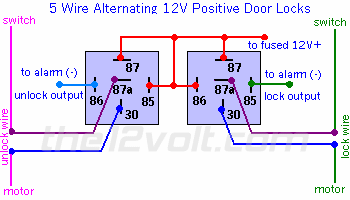
https://www.the12volt.com/doorlocks/page3.asp#5w
If you do not want to unlock the doors, then you only need to use one relay to lock them and you can disregard the other reIay shown for unlocking.
f you need more help, let us know.
the12volt
Hi eloshdesign, like I said in the post above.." If you do not want to unlock the doors, then you only need to use one relay to lock them and you can disregard the other reIay shown for unlocking. " The switch will continue to work as it does now locking and unlocking the doors.
The relay diagram will be the same to use your other channels to lock and unlock the doors. Connect one of your outputs to the coil of the lock relay and the other to the coil of the unlock relay where it shows "to alarm (-) lock output" and " to alarm (-) unlock output" respectively instead of using the door lock outputs from the alarm.
the12volt