12v to 3v conversion
Printed From: the12volt.comForum Name: General Discussion
Forum Discription: General Mobile Electronics Questions and Answers
URL: https://www.the12volt.com/installbay/forum_posts.asp?tid=138350
Printed Date: May 10, 2026 at 2:22 PM
Topic: 12v to 3v conversion
Posted By: jameseric
Subject: 12v to 3v conversion
Date Posted: January 26, 2015 at 8:45 PM
I have 5 devices that use 2 AA batteries each. The batteries keep dying so I want to power all 5 of them with a a single 12 volt battery.
How would you do it?
Thanks,
James
How would you do it?
Thanks,
James
Replies:
Posted By: oldspark
Date Posted: January 27, 2015 at 2:34 AM
A 3V regulator.
And these days, a switched-mode (SMPS) type - not a linear device.
And these days, a switched-mode (SMPS) type - not a linear device.
Posted By: jameseric
Date Posted: January 27, 2015 at 7:16 AM
Oldspark,
Thanks for the reply. Can you please provide some more details? I am not up on electronics so I could use a little spoon feeding. Once I get a better understanding, I can color by numbers. My wife and I have a vegetable garden and every 3-4 week we need to replace the water timer batteries. I would like to wire them to a 12 volt battery that is charged by a small solar panel. I can work out the solar charging but I am unclear on what is needed to run the 5 timers. I hope clarifies my project some more.
James
Posted By: racerjames76
Date Posted: January 27, 2015 at 8:54 AM
IF you are CERTAIN the voltage will never vary some resistors CAN be used, but I as well as OS would probably be more comfortable telling you to use a variable input constant output regulator. When in a car the voltage can vary from 11v-15v under normal operation. That swing will likely be much smaller but I would bet it will be there even on a direct output solar panel. Unless the panel comes fitted with a 12v regulator already. Still...one must consider cloudy days in such calculations...
-------------
To master and control electricity is perfection. *evil laugh*
Posted By: oldspark
Date Posted: January 27, 2015 at 9:25 AM
No problem. Thanks for the added info.
I'll rule out conversion of cig-socket phone charges etc. (I've done a few for 3V but it involves changing one resistor.)
Any idea of the current involved? It's probably not much since it/they run off batteries and hence most (voltage) regulators should handle them.
If you have a DMM or equivalent you could measure the current. If not, you'll need one to adjust the regulator output voltage(s). Sure, you could borrow one, but then how will you check your solar array... is it overcharging or is the battery about to die..?
The above might be options we discuss later.
Switching SMPS voltage regulators...
Tho these giddammit small modern techno "switching" power converters may seem complex, they are almost always cheaper than their old analog counterparts and few would use anything else.
However you said solar and hence IMO they are essential - switching regulators use about 1/4 the power of linear types for a 12V to 3V conversion system.
Did I say small? How's about...
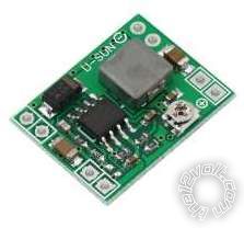
... a thumbnail-sized 3 Amp step-down voltage regulator - eg eBay item 291353891841 (for $1 each???). I've used a few....
Until I considered the LED current I considered these for you...
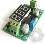
(eg, eBay items 321432207998 221549737814 221670472408 or DHGate.)
Their big advantage is the multiturn adjustment pot (potentiometer = variable resistor) making it so much easier to adjust (try getting an accurate output voltage with those small trimpots in the earlier pic! .. and ensuring it isn't knocked or vibrated).
Another advantage is their screw terminals - no need to solder wires or connectors.
Their 3rd advantage of being able to adjust and check the output voltage using the 3-digit voltmeter (which can also read the input voltage) is their disadvantage for power-critical situations like small solar - unless the meter can be turned off when not required. (I reckon most of its ~20mA "standby" current is due to the display.)
But finding a step-down switching converter (ie, NOT 337 or LM337 types!) with multiturn trimpot and screw terminals and NO voltmeter appears tricky...
However I did find...
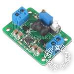
(eBay item 280751515397, but see also dealextremes' offering.)
Or...
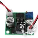
(ebay 121171591143)
... which has connectors.
Are these too DIY for you - would you prefer off the shelf boxed items etc?
Most of the units above feature good over-current protection and at least some have reverse polarity protection.
If you see one with a heatsink make sure it's not a linear type (they'll need the heatsink because whatever power your timers use, the regulator will put out at least 3x as much power as waste heat).
Those switching regulators usually do not have heatsinks tho they can be added for high currents (typically above 2A output).
Housing them can be a PITA - I always reckon the mechanicals of an electric/electronic project is the worst or most tedious part.
But I mounted my "micro" regulator (first pic above) in the engine bay. Tho I conformal coated (sprayed) the unit (except for its trimpot) I merely wrapped it in electrical tape and had is dangling in the engine bay. Tho it did cease to work after a high-pressure engine-bay clean, it came good later. (FYI - I was using it as the tail light voltage to my 3rd brakelight LED bar.)
BTW - I'd suggest buying a few.. Since IMO they are so cheap it's worth having at least one spare if not a few for later projects.
Anyway, your thoughts?
I'll rule out conversion of cig-socket phone charges etc. (I've done a few for 3V but it involves changing one resistor.)
Any idea of the current involved? It's probably not much since it/they run off batteries and hence most (voltage) regulators should handle them.
If you have a DMM or equivalent you could measure the current. If not, you'll need one to adjust the regulator output voltage(s). Sure, you could borrow one, but then how will you check your solar array... is it overcharging or is the battery about to die..?
The above might be options we discuss later.
Switching SMPS voltage regulators...
Tho these giddammit small modern techno "switching" power converters may seem complex, they are almost always cheaper than their old analog counterparts and few would use anything else.
However you said solar and hence IMO they are essential - switching regulators use about 1/4 the power of linear types for a 12V to 3V conversion system.
Did I say small? How's about...
... a thumbnail-sized 3 Amp step-down voltage regulator - eg eBay item 291353891841 (for $1 each???). I've used a few....
Until I considered the LED current I considered these for you...
(eg, eBay items 321432207998 221549737814 221670472408 or DHGate.)
Their big advantage is the multiturn adjustment pot (potentiometer = variable resistor) making it so much easier to adjust (try getting an accurate output voltage with those small trimpots in the earlier pic! .. and ensuring it isn't knocked or vibrated).
Another advantage is their screw terminals - no need to solder wires or connectors.
Their 3rd advantage of being able to adjust and check the output voltage using the 3-digit voltmeter (which can also read the input voltage) is their disadvantage for power-critical situations like small solar - unless the meter can be turned off when not required. (I reckon most of its ~20mA "standby" current is due to the display.)
But finding a step-down switching converter (ie, NOT 337 or LM337 types!) with multiturn trimpot and screw terminals and NO voltmeter appears tricky...
However I did find...
(eBay item 280751515397, but see also dealextremes' offering.)
Or...
(ebay 121171591143)
... which has connectors.
Are these too DIY for you - would you prefer off the shelf boxed items etc?
Most of the units above feature good over-current protection and at least some have reverse polarity protection.
If you see one with a heatsink make sure it's not a linear type (they'll need the heatsink because whatever power your timers use, the regulator will put out at least 3x as much power as waste heat).
Those switching regulators usually do not have heatsinks tho they can be added for high currents (typically above 2A output).
Housing them can be a PITA - I always reckon the mechanicals of an electric/electronic project is the worst or most tedious part.
But I mounted my "micro" regulator (first pic above) in the engine bay. Tho I conformal coated (sprayed) the unit (except for its trimpot) I merely wrapped it in electrical tape and had is dangling in the engine bay. Tho it did cease to work after a high-pressure engine-bay clean, it came good later. (FYI - I was using it as the tail light voltage to my 3rd brakelight LED bar.)
BTW - I'd suggest buying a few.. Since IMO they are so cheap it's worth having at least one spare if not a few for later projects.
Anyway, your thoughts?
Posted By: oldspark
Date Posted: January 27, 2015 at 9:48 AM
I missed racerjames76's reply. I considered a voltage divided chain approach but IMO they get messy. I'd at least use a Zenor regulator across each timer assuming their loading varies (ie, differing currents means simple resistors or series connection probably won't work).
But a regulated solar panel is no different to a car alternator. It tries to maintain a constant (voltage) output of typically 14.4V (maximum) so you have the same ~14.4V down to maybe 12.0V or 11V for a very flat battery. They just happen to be "cleaner" than vehicle systems - no AC input, no slip rings, no voltage spikes, etc.
So hence the usual 12V to maybe 15V voltage range.
If the timer current was known and that it is equal AND constant for all units, then sure, four 3V timers could connected in series to a 12V regulator. But add in the regulator overheads...
So maybe a 9V regulator with series 3 timers or 2 with a suitable series resistor.
But if one unit shorts so others get a higher voltage, or if their current varies...
Nah, IMO it's far better (and simpler & maybe cheaper) having a single 3V source supply all timers in parallel. (Or two 3V sources/regulators if some independence ot redundancy is desired, or if the timers take too much curent for one regulator.)
And for solar, there are no losses thru series resistors or Zener regulators.
Posted By: jameseric
Date Posted: January 27, 2015 at 8:01 PM
Thanks. I gave it quick read. I will out of town for few days. I will dig into it when I return. I have DMM and I can handle the DIY aspect once I am put on track. This is the kind information I wanted. I have until March to get it together.
Thanks again,
James
Thanks again,
James
Posted By: oldspark
Date Posted: January 28, 2015 at 2:03 AM
Sounds good. Maybe the ebay 121171591143 with its 2-pin connectors is ok, but I/we may find others.
Glad too you are not daunted by the new digital (switched-mode) versus the old analog voltage regulators - nor the DIY. The nearly lossless SMPS is definitely the way for solar.
A current reading both when merely idly timing and when switching or with the output (solenoid valve?) on would be nice.
If the timer uses a relay then it may draw up to maybe 250mA extra when the relay is on, but it might use a transistor in which case the "on" current becomes insignificant - eg up to 20mA for a transistor and nothing (well, maybe 10nA) for a MOSFET.
[ Assumptions: Timers do not power the water valves but instead close a relay else ground an output that switches/takes the valve current (at their 12V OR 24V OR whatever...). And only one output "relay" per timer. ]
I'd think it safe to assume no more than 300mA each (and I'm not relating that to their use of AA batteries) and therefore pretty much any of those (types) of regulator I mentioned will handle all 5 timers.
Since best efficiency with SMPS regulators/converters occur at higher loadings - typically being best at 70%-95% of rated output - I'd therefore run all timers off one regulator.
I'd still almost certainly buy another converter/regulator as a spare but I wouldn't worry about splitting loads across 2 regulators for some independence or redundancy (ie, 2 regulators plus one spare).
The above is mainly from a solar efficiency POV but also simplifies wiring (ie, how to connect all to one timer in case the 2nd regulator fails & a replacement is not substituted).
How many regulators I'd get depends on unit & mail costs and how many I'd like for spares or future projects. But low or free postage makes bulk quantity savings negligible, and those regulators have been getting smaller or better or cheaper.
More when you get back into it...
Posted By: jameseric
Date Posted: January 29, 2015 at 6:15 PM
I took a look at the 121171591143 unit. I like it. I think I will order it and start testing. I have project box laying around and the components will be in a waterproof garden box. I have a few solar battery chargers which should be enough for my small load. If not, I will use a larger panel.
Thanks for your help. I am truly grateful. You have given me a good place to start. Unless I am missing something it looks like I just need to make the connections and set the voltage.
James
Thanks for your help. I am truly grateful. You have given me a good place to start. Unless I am missing something it looks like I just need to make the connections and set the voltage.
James
Posted By: oldspark
Date Posted: January 29, 2015 at 8:29 PM
I like your choice. Not that I've used that one, but IMO they should all be good.
It has the usual short circuit protection & current limiting, as well as input polarity protection.
And it has the multi-turn (10 turn??) trimpot.
I like its layout and shape.
Sure, it's now "old tech" using a 150kHz LM2596 (modern equivalents switch at 10x that frequency), but it's a proven chip and higher frequency usually only mean a smaller total sized module (smaller inductor/coil & smaller caps) and a minor gain in efficiency - neither if which IMO are an issue in this case. (Besides, some things can be too small.)
And I like its connectors as a compromise between relatively large screw terminals and having to solder one's own (which on mine are plain header pins; else wires that are easy to break).
And tho screw terminals may be easier for "universal" or one-off use, pluggable connectors are bluddy nice when it comes to replacement etc.
Oh yeah - they are common 2-pin connectors - same as 2-wire/pin fans as used in PCs and MANY other circuits.
And yes, it's merely a case of connecting and setting.
I suggest setting low first if not able to correctly adjust before connecting the load, then adjust up. (Overvoltage kills fast whereas undervoltage is rarely a problem during initial connection.)
Usually such regulators can be adjusted with any voltage input (within its specified 4.5-40V range) and without a load, however some might require a minimum load (current) for correct regulation tho that should (& IMO MUST!!) be specified i its description. (Minimum loads usually do not apply to switchmode converters tho some (older?) PC power supplies are typical exceptions.
But your testing should (1) confirm pot rotation direction for minimum output & (2) if (re-)adjustment is required after the load is connected (I'm betting not).
If it does output too high (or doesn't react at all) without a load, use any non-sensitive load for the adjustment - eg, a resistor or bulb or LED - but worry about that if needed after your testing.
FWIW - hats off to you! I love people getting into such "oh so difficult (& beyond me?)" newish hitech thingies - especially when it replaces fiscally & environmentally costly batteries or distribution with a (IMO) far superior "master" power system - especially rechargeables like 12V solar.
Posted By: jameseric
Date Posted: January 29, 2015 at 10:11 PM
Thanks again for detailed research and advice. I look forward to putting it all together. I may take a few months to get around to it, but I will post pictures when it is done.
James
James
Posted By: jameseric
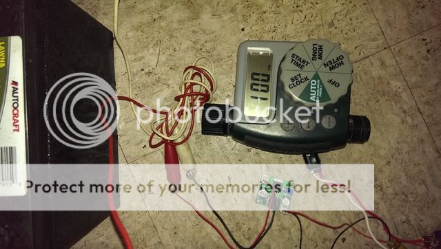
Date Posted: March 26, 2015 at 5:31 PM
Oldspark,
It worked just as you suggested. I soldered the connections and it is working fine. I will connect the other 5 timers and a solar panel and let it run all summer.
Thanks a million,
James

 [/IMG]
It worked just as you suggested. I soldered the connections and it is working fine. I will connect the other 5 timers and a solar panel and let it run all summer.
Thanks a million,
James
[/IMG]Posted By: oldspark
Date Posted: March 26, 2015 at 7:24 PM
James - thank you 2-million! Great to get your update and a working pic (which already looks as permanently installed as many of my projects LOL).
I see you went with the eBay 121171591143 LM2596 DC-DC Step Down Module. I'll consider that for my future buys - its connectors are a nice addition and it has the common reverse polarity and overload protection and multiturn pot.
Even tho your timers might do with far sloppier voltage regulation using mere resistors or zeners, IMO the LM2596's fourfold power consumption difference from 12V is a massive advantage. IE a 12V battery will last 4x longer, or can be 4x smaller etc. Or 2x if using a 6V battery.
Look for lot's of five etc deals for that or similar converters. Not that I'd normally risk big bucks on an unsampled bulk buy but such converters are mature technology and I have yet to find any duds. (Maybe 3-4 different buys of lots of 5; all tested tho only a few used in practice.)
And I always buy extra for convenience or spares - especially if postage costs are high (and units cheap) - tho mine are almost always ex-China with free postage... dang! - can't use unit versus postage cost to help determine optimum quantity buy.
Incidentally, you'll probably find that after setting the trimpot and attaching the connectors you can seal the module - eg, coat with some conformal coating - except perhaps if running nearer to 2A output without heatsinking.
I'll often spray 2 coats of PCB Lacquer before dangling my things in engine bays etc. My 1.2MHz dc-dc converter worked fine like that - I suspect its temporary outage after a high pressure wash had more to do with its distant connectors that may have water-shorted.
My point being that you can probably stick the LM2596 modules to the back of the timers etc rather than the trouble of a housing etc.
Otherwise co-locate the modules in a box near the battery or solar regulator etc. Which location method depends on situation & preference. EG - dc-dc converters are usually at the load end for long transmission distances to compensate for voltage drops, or where mere end replacement does both converter & timer. Otherwise central colocation of modules may be the more desirable.
Anyhow, best wishes. I hope the modules prove reliable (I'm sure they will).
Lifetime cost $aving$ could be an interesting followup tho you said ~monthly replacement of 2 AA batts so using my calcs... two Aldi 25c AA cells => 50c/month so after 12 months you're ahead excluding solar & 12V batt costs.
Then there's the maintenance free and "set & forget" aspect...
Posted By: jameseric
Date Posted: March 27, 2015 at 5:54 PM
First, due to low water pressure, we only open one timer at a time. The module is rated for 10A. I planned on using one module and running the timers in parallel unless that is a bad idea. If that presents a problem I can always add 4 more modules. I plan to buy spares anyway. I prefer to place them near the battery and solar panel in a protective case. My only concern is condensation if the case sweats. My design takes into account the line drop over the longest run of 30 feet.
Posted By: oldspark
Date Posted: March 27, 2015 at 7:22 PM
By module do you mean the dc-dc converter? (Because isn't that only rated for 2A else 3A with heatsinking etc?)
If you mean something else then fine. (eg solar module etc)
Timers in parallel should be fine. IE - I think your timer/valves were all low current and one dc-dc conv may handle all or more than one. (Unless that's the 10A module you referred to in which case it's a peak load and might still be ok...?)
Plus the dc-dc conv is supposedly self protecting and should shutdown in case of overcurrent (rather than cause a brownout situation that can damage loads). If so, a power cycle resets the dc-dc conv. [ If it does limit current but continue to supply at a lower voltage like analog/linear voltage regulators do, then beware - the timers/valves may not like it! ]
One concern might be simultaneous power-on or switching of valves resulting in current surges but they are likely to be short and handled by the dc-dc conv.
And maybe capacitor(s)... But see if you have behavior problems. I'm thinking maybe a small cap to act as a filter against valve transients, and maybe a larger cap for current-surge ride-thru, but that/they might have issues (but probably not).
Again, some sort of PCB coating should negate condensation issues.
And you are taking into account your run lengths (yay!) and hence using my generally preferred centralised solution. (Unlike and old example of a 200m cable to a camera where the converter was therefore placed at the camera end.)
Being battery powered, the voltage probably isn't too critical. IE - typical alkaline batts are up to 1.65V hence your timers should tolerate 3.3V if not 3.6V for other cell types. And it might operate anywhere down to ~2.0V tho I'd assume not that low... maybe 2.7V???
If they were solenoid type valves I'd probably adjust the vregs (dc-dc convs) for 3.0V at the valve end with valve energised provided 3.6V is not exceeded with valves de-energised.
But if they are motorised and only draw current whilst changing state I'd merely ensure they operate ok at whatever voltage you set tho I might then set for a higher voltage, say 3.2 - 3.5V.
Circuits like this can be tricky. The timer might handle 5V or more but solenoids can burn out with overvoltage (ie, overcurrent) and motors can burn out with undervoltage - ie, they never develop the power to get there so they just heat up.
Luckily electromagnetic devices like that tend to be quite robust and tolerate relatively large deviations from "nominal" operational voltage for reasonable times.
There's also the impact upon overall current draw from the battery but I doubt that's a concern and it would probably only be 20% difference if that.
Posted By: jameseric
Date Posted: March 27, 2015 at 9:37 PM
Thanks again. 3.5v should drop to 2.7v at 30 feet. I feel safe at 3.5v. I will run more test over the weekend and post back.