So I'm adding an e-fan to my 09' F150 and I'm looking to get some opinions on the circuit I designed to power both the low and high windings. The idea here is to tie the low side to a temp sensor (that will be mounted in the upper radiator hose via a 1/8 NPT sensor with 200* on/185* off), and the high side to the AC clutch engage voltage. But since this motor isn't one that can take both sides being powered at the same time I had to find a way to kill the low side when the high is engaged.
I've tried the URL button but each time I test it I get a 404. So here's my own image:
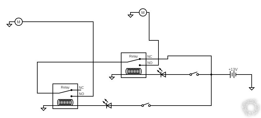
First thing you will notice is the two toggles. That website didn't have objects to represent an AC clutch or a temp switch.
For current load, the low side is ~6-10A the high side anywhere from ~20-30A. The relays I'm using are 30A rated as well as the fuses.
Secondary question if I may.. If anyone knows of a good resource (website, IOS app, etc) to help with circuit design and maybe to let you test the flow please let me know because that'd be awesome!
Thanks!
The relay with the 5 connections is your high speed relay. Circuit as shown will never operate high speed, no power applied to high speed winding. Needs the common terminal to connect to battery. The normally closed terminal connects to the common of the low speed relay.