How can I fix this circuit?
Printed From: the12volt.com
Forum Name: General Discussion
Forum Discription: General Mobile Electronics Questions and Answers
URL: https://www.the12volt.com/installbay/forum_posts.asp?tid=178
Printed Date: April 26, 2026 at 8:40 AM
Topic: How can I fix this circuit?
Posted By: eloshdesign
Subject: How can I fix this circuit?
Date Posted: March 29, 2002 at 6:26 PM
Please take a look at the attached diagram. The manual rocker switch was hooked up and worked fine. When I added the dual relay circuit (for remote control) the fuse at the switch would blow when I pressed up or down on the switch. I can have either remote control or manual control, but not both at the same time. Looking at the diagram, why is this happening and how can I fix it so both methods can get along? The pulse stretcher is not actually hooked up yet. Thanks, Daren 
Replies:
Posted By: the12volt
Date Posted: March 29, 2002 at 11:08 PM
Hi eloshdesign, the fix is simple, you need to cut each lead from the switch to the actuator and connect 87a to the switch side of the respective actuator lead and connect 30 to the motor side of the respective actuator lead. the12volt
Posted By: the12volt
Date Posted: March 29, 2002 at 11:17 PM
BTW, if you need me to draw a diagram of the workling circuit, just let me know. the12volt
Posted By: delosh
Date Posted: March 30, 2002 at 12:30 AM
I would love a diagram. Could you please do one up for me?
Thanks,
Daren
Posted By: delosh
Date Posted: March 30, 2002 at 8:31 AM
I read it again today
it's much clearer now.
Note to self: Do not try to figure out electronic circuits AFTER the neighbors come over for drinks.
Thanks!
Daren
Posted By: the12volt
Date Posted: March 30, 2002 at 10:49 AM
Hi Daren, here ya go: 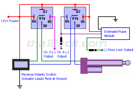
Let me know if you need anything else. the12volt
Posted By: eloshdesign
Date Posted: March 30, 2002 at 12:24 PM
Thanks for the diagram.
I wired it just like you have it in the above diagram, but the actuators don't move via the alarm remote. The manual switch works and the 30's light up my test light via the alarm remote (when the test light is grounded to the chassis). Are the actuators not getting ground somehow when activated vis the remote?
Thanks
Posted By: the12volt
Date Posted: March 30, 2002 at 1:09 PM
Hi eloshddesign, measure resistance to ground on each actuator lead at the actuators. If they are not resting at ground with nothing activated, then I'd suggest rewiring your switch so the actuators do rest at ground or even wire the switch to activate the coils of the relays to control the actuators. the12volt
Posted By: eloshdesign
Date Posted: March 30, 2002 at 1:15 PM
Would it be possible to do another diagram that shows the above options? It's a little unclear to me about "resting at ground". Does that mean the switch needs to grounded all the time?
Thanks
Posted By: the12volt
Date Posted: March 30, 2002 at 1:29 PM
Here's a diagram showing the switch activatiing the coils of the relays to control the actuators. 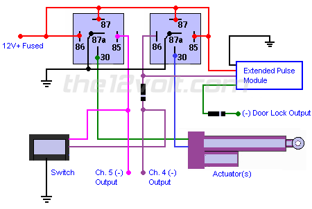
the12volt
Posted By: eloshdesign
Date Posted: April 01, 2002 at 7:51 PM
Hey the12volt,
I just wanted to say thank you very much for the diagrams! The last one worked perfect for controlling the actuators from the remote and the switch.
The only problem now is the extended pulse module did not activate the actuators on arm. The LED in the module and my test light turn on when I arm, but the actuators did nothing. Also, each time I moved the actuators down, I had to wait the 5 second delay until I could go up. No big deal for now. It's a luxury I will address later.
Thanks again!
Daren
Posted By: the12volt
Date Posted: April 01, 2002 at 7:57 PM
Hi Daren, do you have a positive or negative output from the extended pulse module? In my diagram, I'm assuming you have a negative output. If you have a positive output, you can simply add another relay to solve your problem. BTW, you're welcome, glad I could help. the12volt
Posted By: eloshdesign
Date Posted: April 01, 2002 at 8:01 PM
You're right. The test light was grounded, so it's a positive output. Any chance I could see that in picture format?
Thanks,
Daren
Posted By: the12volt
Date Posted: April 01, 2002 at 9:22 PM
Hi Daren, here ya go: 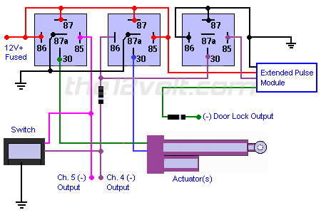
the12volt
Posted By: eloshdesign
Date Posted: April 02, 2002 at 9:52 AM
Thanks!
Will I still have to wait for 5 seconds (extended pulse setting) after pressing down before I can go back up? If so, is there a workaround?
Daren
Posted By: the12volt
Date Posted: April 02, 2002 at 9:58 AM
Hi Daren, you're welcome. Please explain exactly when you get this 5 second delay and does it exist when you use the switch, door lock output, or channel 4 and/or 5? the12volt
Posted By: eloshdesign
Date Posted: April 02, 2002 at 10:06 AM
The delay is the Extended Pulse Module's output. It is set to hold it's ouput on for about 5 seconds. This is so when I arm the alarm, the module will lower the actuators (for about 5 seconds).
I noticed when I had it hooked up the other day, I had to wait for the 5 second duration (after I moved them down) before I could push them back up. During this 5 second wait, the extended pulse module's LED was lit up. So, the ext pulse module is kinda interfering with the switch and remote operation. Does that make more sense?
Posted By: the12volt
Date Posted: April 02, 2002 at 10:21 AM
Hi Daren, yes, I see what's happening. The only work around would be to add another relay activated by the switch and channel 5 to interupt the extended pulse module's output to allow you to raise the actuators immediately after you've activated the module. the12volt
Posted By: eloshdesign
Date Posted: April 02, 2002 at 12:10 PM
|