I have a 1993 honda accord sedan and have done my research to what wires do what. This is my first post to thi forum and I do have a vast knowledge of electronics and wiring history.
My question begins with that I am wiring 4 - 12 inch cold cathode light tubes in my car with to inverters. The inverters accept 12v +/- .75 volts. My intent for the lights were to come on when the door opened or you could switch them on manualy. I used a SPDT switch to seperate the grounds, since the dome light is ground activated. I have the power running through a 12v voltage regulator then to the inverters. My big problem is that the car produces around 13.6 volts. The input voltage on the IC regulator is 14 to 30 vdc. Since the voltage regulator is not getting the correct input voltage, I am getting a voltage drop for an output voltage of 10 to 10.6. How can I increase the voltage to make the inverters see a constant 12 volts or to up the input voltage on the regulator to say 24vdc so it will be well in to the input voltage range.
My knowledge from Electronics school has faded over the years, but I don't think you can use a tranformer to up dc voltage with out converting it to ac then back to dc. Any ideas would be great.
You could try a low dropout voltage regulator to supply power to the tubes. Try www.mouser.com. They usually need only a half volt difference to regulate properly. Not sure of the power requirements of each as i'm not familiar with CCFL inverters. They do have various voltage, (adjustable also) and current ratings to the regulators. If the tubes operate fine at 11.25 volts, you could set an adjustable unit to that voltage, which in theory, would allow them to operate with a battery voltage as low as 11.75. That should allow them to operate as you desire. May require tweaks to the circuitry, but then again, somethings always do. Hope this helps.
Mark M
I went today after the vehicle has been sitting since last weekend, I guess my voltage regulator is shot because i'm only getting 4.25 volts out of it. I checked my input voltage and with the care off I'm getting 12.7 and with the engine running I'm getting 14.1 volts.
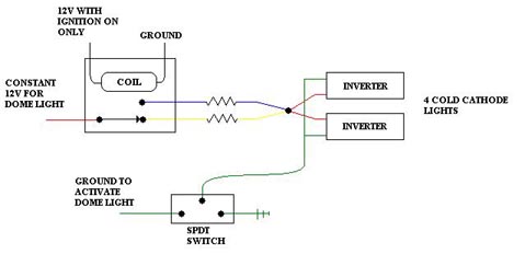
I'm kinda come up with an idea with a relay thats wired in with the ignition. I'll post a diagram of what I'm talking about once I figure out the resistor values.
Here's the diagram. I haven't thought about the resistor values yet. I need to find out what the load of the inverters and lights are.