Odd request. Circuit diagram needed.
Printed From: the12volt.com
Forum Name: General Discussion
Forum Discription: General Mobile Electronics Questions and Answers
URL: https://www.the12volt.com/installbay/forum_posts.asp?tid=76189
Printed Date: May 14, 2026 at 8:35 AM
Topic: Odd request. Circuit diagram needed.
Posted By: overworked2
Subject: Odd request. Circuit diagram needed.
Date Posted: April 13, 2006 at 7:49 PM
Hey guys, this is a little bit of an odd request and I hope someone can whip the schematics up for me. I have a light bar on my car that I wired in and now I need to create a circuit diagram for my portfolio that I need tomorrow. My issue is that I don't have any programs that do it nor do I have the expertise to use them. I was wondering if someone could create a diagram from my instructions? Please? Anyone! LOL Anyways, here the layout.
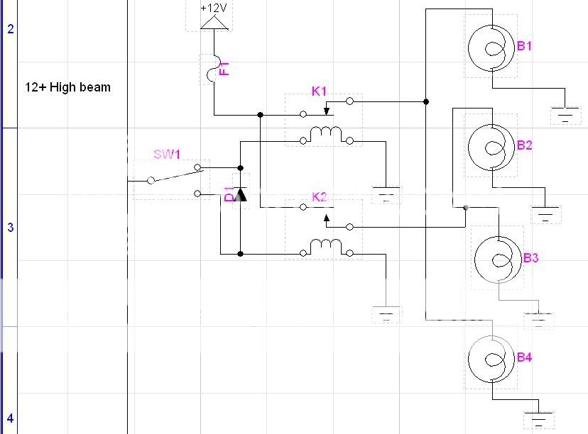
4 Spot lights powered in pairs. An inside pair and an outside pair.
I've taken my positive high beam feed from the headlight switch and fed that to a SPDT switch.
One output from the switch goes to pin 86 on relay 1 and then goes through a diode to pin 86 on the second relay.
The second output goes to pin86 on the second relay and is stopped by the diode.
A single power wire is ran from the battery to the two relays with a 25amp fuse.
If anyone needs clarification questions please ask as I really appreciate anyone helping me.
-------------
Check all advice given with a meter
Replies:
Posted By: the12volt
Date Posted: April 13, 2006 at 8:02 PM
You might think I'm joking, but if you're running Windows, you could always use MS Paint. It's great for line art. Start>Programs>Accessories>Paint -------------  the12volt Support the12volt.com the12volt Support the12volt.com
Posted By: overworked2
Date Posted: April 13, 2006 at 8:05 PM
I know your not joking as thats how I've always done them before but this time I really need it professional looking...not just a scribble for my own memory or to pound into my trainees head :D
I have downloaded a trial program and I found the simple symbols that I need...now if only I can get it so I can cross my grounds over the top of my power lines without it looking like a short circuit :)
-------------
Check all advice given with a meter
Posted By: the12volt
Date Posted: April 13, 2006 at 8:11 PM
If you're using different colors and not indicating a connection where they cross, it should be obvious that there is no connection where they cross. Here's an example, done it Paint. 
------------- the12volt Support the12volt.com
Posted By: overworked2
Date Posted: April 13, 2006 at 8:17 PM
Thanks for the advice 12volt I will use it if you guys don't think this is suitable... 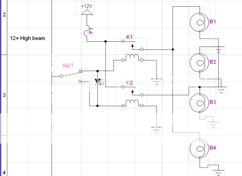 ------------- Check all advice given with a meter
Posted By: overworked2
Date Posted: April 13, 2006 at 8:18 PM
oh dear...it shows K1 as being open whilst the Switch is on it's side.... :(
-------------
Check all advice given with a meter
Posted By: overworked2
Date Posted: April 13, 2006 at 8:19 PM
ahh wait...I've found some other issues that occured when I re arranged the lights....the grounds are looking odd.
-------------
Check all advice given with a meter
Posted By: overworked2
Date Posted: April 13, 2006 at 8:28 PM
 ------------- Check all advice given with a meter
Posted By: overworked2
Date Posted: April 18, 2006 at 4:38 AM
Ok, so what I didn't tell you guys is that it was for a portfolio for a job as a bestbuy installer. I had the interview and it all went great.
But, the HEAD installer had to have the circuit diagram explained to him and then asked me if the diode was to stop noise from entering the radio. 
I just want to work back in my field but whats up with isntallers these days? How the hell did he become a manager when his knowledge is not upto scratch. ------------- Check all advice given with a meter
Posted By: overworked2
Date Posted: April 18, 2006 at 4:45 AM
on another note. He asked me what the difference is between a standard relay and a Bosch relay was. I didn't know there was one and he didn't give me an answer when I said that I wasn't aware of any differences between a "standard" relay and a Bosch 4 pin. When queried he confirmed that he was talking abbout the 4pin relay with pins 85, 86, 87 and 30.
-------------
Check all advice given with a meter
|