Im trying to figure out how I can create a circuit that excepts multiple signals(max three) and then outputs a single one (something like a lock) I also requre it to only output if all three are inputed.. This may be a simple plan for some of you but my knowledge is limited
You can use this chip
https://www.jameco.com/Jameco/Products/ProdDS/295777.pdf
you can also use relays:
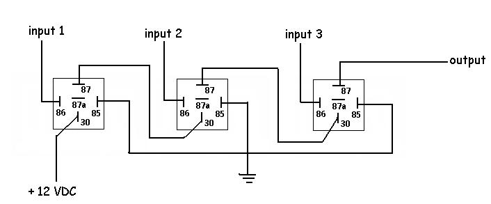
The output will only be on if all three inputs are on, and the inputs are all 12VDC.
fakepete wrote:
You can use this chip
https://www.jameco.com/Jameco/Products/ProdDS/295777.pdf
Technically this will work because it is an AND gate, but it is designed for TTL logic which uses 0v=Low 5v=High and so you have a few problems. First the input voltage cannot be greater than 5v, same with the source. Also the output will not exceed 5v. Assuming that this is going to be used in a 12v system (this is the12volt.com after all) it makes the idea slightly more complex.
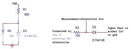
I would say that I know of two solutions that would use an AND gate, first would be a circuit that has 5v Zeners on the input pins so that a low will still be 0v and a ~12v input will be regulated to ~5v, also some form of a 5v regulator for the source like a 7805, then on the output some kind of transistor to source/sink the necessary current depending on the load possibly a relay.
This picture shows what I mean by the Zener. It is the left circuit, the logic chip input is between the ~600ohm resistor and the Zener diode, this could be used assuming that the input will be pulled high when on and either floating or low when off. The right circuit is for allowing an input to pull the pin low, and leave the pin at 5v when the input is high.
The other way would be to use CMOS logic chips, they are capable of source voltages up to 18v, the main problem is that they are extremely sensitive to static electricity so you will need to design around that downfall. I don't know what to do to eliminate this problem so pursuing this idea is up to you.