amp gauge
Printed From: the12volt.com
Forum Name: General Discussion
Forum Discription: General Mobile Electronics Questions and Answers
URL: https://www.the12volt.com/installbay/forum_posts.asp?tid=99775
Printed Date: May 14, 2026 at 5:28 AM
Topic: amp gauge
Posted By: mag63
Subject: amp gauge
Date Posted: December 08, 2007 at 2:56 AM
Hey guys I have an amps gauge in my shop type battery tester that someone has replaced an I don't think it's wired up correctly!!
How would you wire that gauge?
Only has 2 terminals on the back of the gauge, 1 marked + and the other 1 marked - I know it's not + and - like in a volts gauge..  ------------- I use to be confused but now I'm not so sure:)
Replies:
Posted By: mag63
Date Posted: December 08, 2007 at 3:38 AM
added some pics    ------------- I use to be confused but now I'm not so sure:)
Posted By: i am an idiot
Date Posted: December 08, 2007 at 8:26 PM
Why do you think it was improperly connected? Was it pegged out for a while and now it is stuck in the position on the picture? There is a positive and negative connection on the meter, but it is to be connected across a shunt and probably is to have a resistor run in series with it. A shunt is going to be a short metal rod probably smaller than the wires that connect to it. Do you see this on your charger?
Posted By: mag63
Date Posted: December 08, 2007 at 8:50 PM
Thanks 4 answering my post but i'm just on my way out, so I will get back to you later today thanks again  ------------- I use to be confused but now I'm not so sure:)
Posted By: mag63
Date Posted: December 09, 2007 at 3:42 AM
i am an idiot wrote:
Why do you think it was improperly connected? Was it pegged out for a while and now it is stuck in the position on the picture? There is a positive and negative connection on the meter, but it is to be connected across a shunt and probably is to have a resistor run in series with it. A shunt is going to be a short metal rod probably smaller than the wires that connect to it. Do you see this on your charger?
Thanks again I.A.A.I.
Yes it was pegged out and the needle still moves 
The shunt I have a look for it.
There is a resistor inside the gauge connected between both terminals...
 border="0">
<a href="https://photobucket.com"><img src="https://i179.photobucket.com/albums/w295/mag63/Picture002-2.jpg" alt="Photo Sharing and Video Hosting at Photobucket"></a>
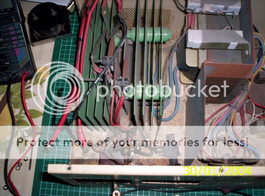
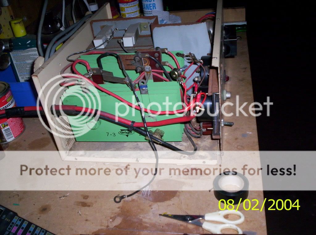
OK the fat 2 red cables with the eyelets was connected on each of the terminals on the gauge.
There is a black cable on the top (with white writing) that has an eyelet on it and that 1 had been taped up and pushed to the bottom of the case out the way..
Are the pics good enough for you to see what I'm telling you about?? ------------- I use to be confused but now I'm not so sure:)
Posted By: mag63
Date Posted: December 09, 2007 at 3:50 AM
 ------------- I use to be confused but now I'm not so sure:)
Posted By: mag63
Date Posted: December 09, 2007 at 3:59 AM
And this pic  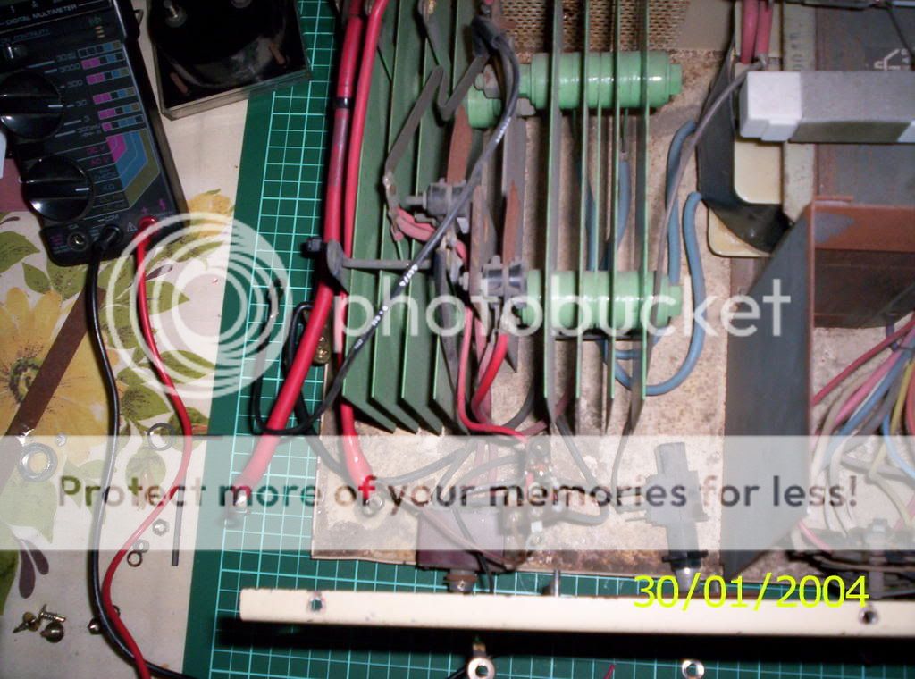 ------------- I use to be confused but now I'm not so sure:)
Posted By: i am an idiot
Date Posted: December 09, 2007 at 5:57 AM
Looks like the old meter may have had the shunt mounted to it. Was there a metal rod or a metal bar mounted to the back of it?
Posted By: mag63
Date Posted: December 09, 2007 at 6:10 AM
i am an idiot wrote:
Looks like the old meter may have had the shunt mounted to it. Was there a metal rod or a metal bar mounted to the back of it?
Thanks, No didn't have any thing on the back of the new gauge, I might ask the old owner if he still has the old amps gauge still??
If not what would you suggest next? ------------- I use to be confused but now I'm not so sure:)
Posted By: mag63
Date Posted: December 09, 2007 at 6:46 PM
mag63] wrote:
i am an idiot wrote:
Looks like the old meter may have had the shunt mounted to it. Was there a metal rod or a metal bar mounted to the back of it?
Thanks, No didn't have any thing on the back of the new gauge, I might ask the old owner if he still has the old amps gauge still??
If not what would you suggest next?
But thinking about that  even if he still had the shut it would be no good 4 this gauge as the internal resistance would be different...
I could make 1 from copper wire of the right gauge and spiral wind it to make it neat and to shrink the size of it as the straight wire would be 2-3ft long ------------- I use to be confused but now I'm not so sure:)
Posted By: i am an idiot
Date Posted: December 09, 2007 at 8:29 PM
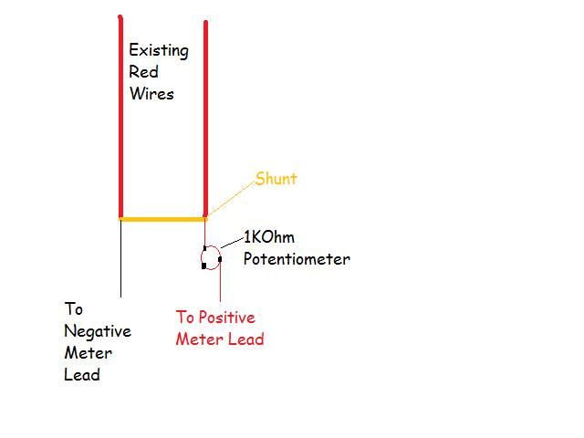
The shunt needs to be only a few inches long. You could go to a hardware store and get a piece of solid ground wire, and some solder on ring terminals. It would be better to not attach the shunt near the meter this time. I am sure that the heat from the shunt is what toasted the original meter. The 2 red wires that I see in the picture need to be connected to the shunt. One wire to each end of the shunt. You need to run 2 smaller wires from the same 2 junctions to the meter. You will need to insert a 1K ohm potentiometer in series with one of the wires going to the meter. This will be the adjustment to calibrate the meter. You will need to figure out which of the 2 wires goes toward the positive connection of the tester. That junction needs to go to the positive connection of the meter.
Posted By: mag63
Date Posted: December 09, 2007 at 8:49 PM
Fantastic mate 
I mostly follow what you're saying would it be to much to ask for a wiring diagram as I could follow that better
Also the solid copper wire what thickness would you recommend?
Thanking you for your time and patience...
Mark... ------------- I use to be confused but now I'm not so sure:)
Posted By: i am an idiot
Date Posted: December 09, 2007 at 9:37 PM
Posted By: mag63
Date Posted: December 10, 2007 at 6:40 AM
Mate how good are you 
Hi again what would be your choice of the 2??
Pot 16mm 1 kOhm SG/Lin (B)
200mW 200VDC Spline 18 Teeth
Cat No. R7551
Category: 16mm Single Gang
Product Image
A$1.89 incl GST
OR
Pot 16mm 1 kOhm SG/Log (A)
100mW 150VDC Spline 18 Teeth
Cat No. R7502
Category: 16mm Single Gang
Product Image
A$1.89 incl GST
"go to a hardware store and get a piece of solid ground wire", what thickness does this need to be as It would have to cope with at least 40 amps is my way of thinking..
Mark.. ------------- I use to be confused but now I'm not so sure:)
Posted By: i am an idiot
Date Posted: December 10, 2007 at 5:59 PM
The pot is not that critical just get the cheapest thing available. We may have to get a different value. The 1k is just to get the meter working, we may have to get a different value for actual accurate calibration. If you are only dealing with 40 amps you could use an AGU 60 as your shunt. Please get a Buss Brand silver fuse. If you use the AGU fuse as a shunt you will need to get a good fuse holder. Do not use a sealed one as sold by every Car Audio Accessory manufacturer. They are sealed and the heat has no where to go. Use one found on the bottom of this page. Middle row of pictures second from bottom. https://www.webnevesht.com/products/Fuses-Buss.aspx The description reads Buss Bussman Single Pole Fuse Block BM6031PQ NEW $ 2.95 I know it is only rated at 30 amps. It is severly underrated.
Posted By: mag63
Date Posted: December 11, 2007 at 12:49 AM
Hi again, I had a look at the link you sent and I am having trouble finding that Bussman part here in Australia  I am waiting for a call back from the Australian agent as that part No. does not come up on their PC.. Also have sent a email to the Ebay person on your link about getting 1 sent here if I win the bid.. ------------- I use to be confused but now I'm not so sure:)
Posted By: i am an idiot
Date Posted: December 11, 2007 at 6:02 AM
I didn't notice your location. The ground wire from the hardware store will work just fine. Just get something that will handle 40 amps of current.
Posted By: mag63
Date Posted: December 11, 2007 at 6:12 AM
Hey that's cool
OK I'm off to the hardware tomorrow then and I'll see what they have for me
That's why at times there's a delay in posts, bloody time zones  ------------- I use to be confused but now I'm not so sure:)
Posted By: mag63
Date Posted: December 12, 2007 at 9:35 PM
Hi yes it's me The hardware had nothing, well 20amp was the best.. Went to 2 more the same and by then I had smoke coming out of my ears  Went to a metal salvage yard no go either and finely to an electrical wholesaler and also NO but I told him It was for making a shunt for an amps gauge and he come up with a idea< how about this a section of bus-bar and will handle 80amps the smallest length we have, Sold... I'll cut of 4 off the fingers and use the flat bar!!! To the eletronics shop this afternoon for the potentiometer 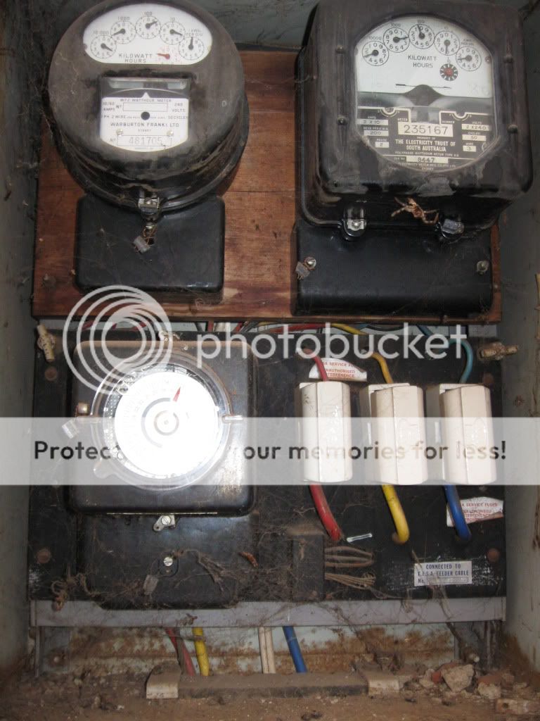 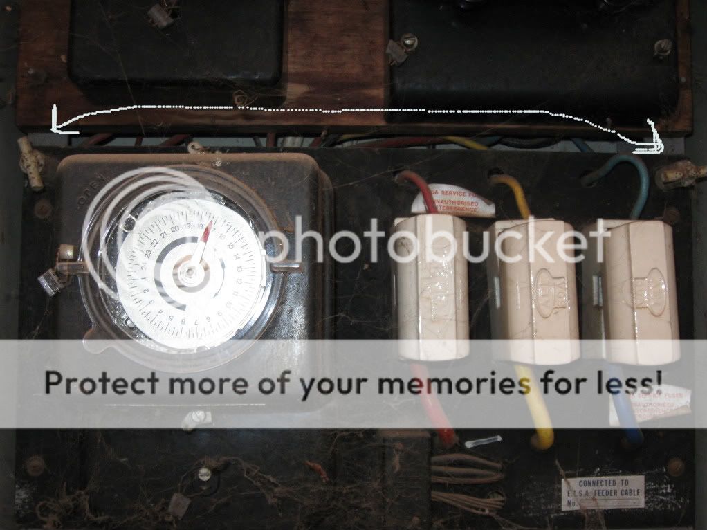 ------------- I use to be confused but now I'm not so sure:)
Posted By: mag63
Date Posted: December 14, 2007 at 6:10 AM
Nothing to report yet haven't had the time, will soon ------------- I use to be confused but now I'm not so sure:)
Posted By: i am an idiot
Date Posted: December 14, 2007 at 8:15 AM
The bus bar should work just fine.
Posted By: mag63
Date Posted: December 16, 2007 at 2:18 AM
Hi an update
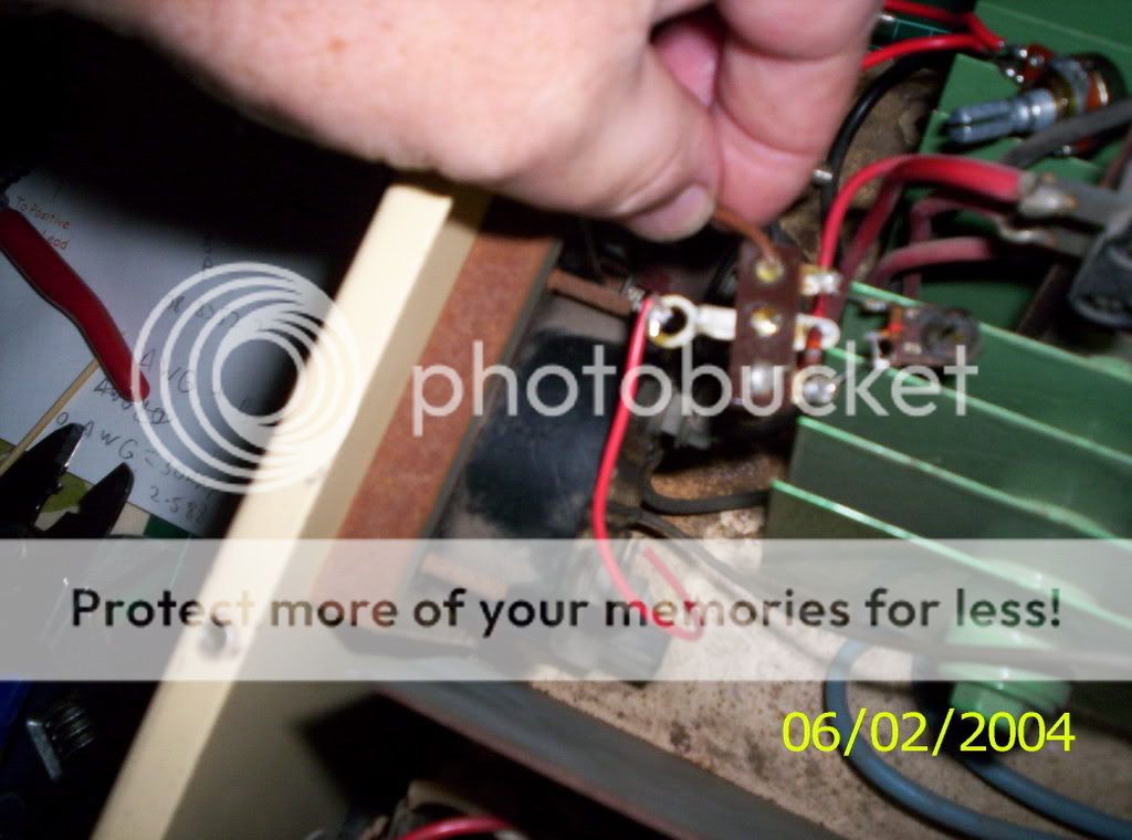
Have done the mods and doing some reassembly and was checking a few things before test firing, that little trim pot on page 1 of this post has 2 small brown Resistors on it and 1 of them has NO reading on the multi meter (fried) but the bands on it are had to see.
Looks like RED / ORANGE / blue gold and if that's correct it is 23M ohms!
If you zoom in on the pic what do you think? am I correct? ------------- I use to be confused but now I'm not so sure:)
Posted By: i am an idiot
Date Posted: December 16, 2007 at 6:37 AM
I didn't even notice the potentiometer in your picture. The resistor colors you gave would be 2.3 Meg What parts of the pot and resistors are fried? How many small wires are there going to the pot assembly? The pot on the unit and the resistors on it were calibrated for the original shunt. But they are already there and configured for what we were trying to build. Do you know how to use the Macro Function of your digital camera? It is the selection with a flower on it? It allows you to take close up pictures.
Posted By: mag63
Date Posted: December 16, 2007 at 6:51 AM
Hi again
No that 1 is for the volt gauge or is that hooked up wrong too!
Macro on my camera? never used it I'm going to have a look right now ------------- I use to be confused but now I'm not so sure:)
Posted By: mag63
Date Posted: December 16, 2007 at 7:16 AM
I had a look and don't see Macro (flower setting) anywhere
I know it's on my Dad's camera (he can't even work the zoom)
this pic any better? ------------- I use to be confused but now I'm not so sure:)
Posted By: i am an idiot
Date Posted: December 16, 2007 at 9:21 AM
Yes all of that looks like it is for the volt meter. The pot looks pretty charred. We will have to continue as planned.
Posted By: mag63
Date Posted: December 16, 2007 at 7:25 PM
OK then lets go as planned
What's next??  ------------- I use to be confused but now I'm not so sure:)
Posted By: i am an idiot
Date Posted: December 16, 2007 at 8:21 PM
Drill holes in the shunt, connect the wires with a Bolt and Nut, connect the small wires that go to the meter and to the pot. You will have to mount the shunt somehow. It can not touch the metal of the frame.
Posted By: mag63
Date Posted: December 17, 2007 at 12:14 AM
i am an idiot wrote:
Drill holes in the shunt, connect the wires with a Bolt and Nut, connect the small wires that go to the meter and to the pot. You will have to mount the shunt somehow. It can not touch the metal of the frame.
Hi, have done as above but can't find anywhere to mount the shut without earthing it out , can I wrap it in electrical tape or is heat going to be a problem?
Thanks... ------------- I use to be confused but now I'm not so sure:)
Posted By: i am an idiot
Date Posted: December 17, 2007 at 3:55 AM
I do not know how hot it will get. You can wrap it in tape but you will have to monitor it the first few times you use it.
Posted By: mag63
Date Posted: December 17, 2007 at 5:57 AM
No worries mate, I have moved it to the shed and will just try it and if all is good I will try to make something to mount the shut on...
What's next do you think?
-------------
I use to be confused but now I'm not so sure:)
Posted By: i am an idiot
Date Posted: December 17, 2007 at 5:55 PM
Just turn the potentiometer you added to the point of maximum resistance. put a battery on it and press the load switch. Turn the pot untill the meter moves. You may have to test a couple of known good batteries to see how the meter acts.
Posted By: mag63
Date Posted: December 17, 2007 at 8:13 PM
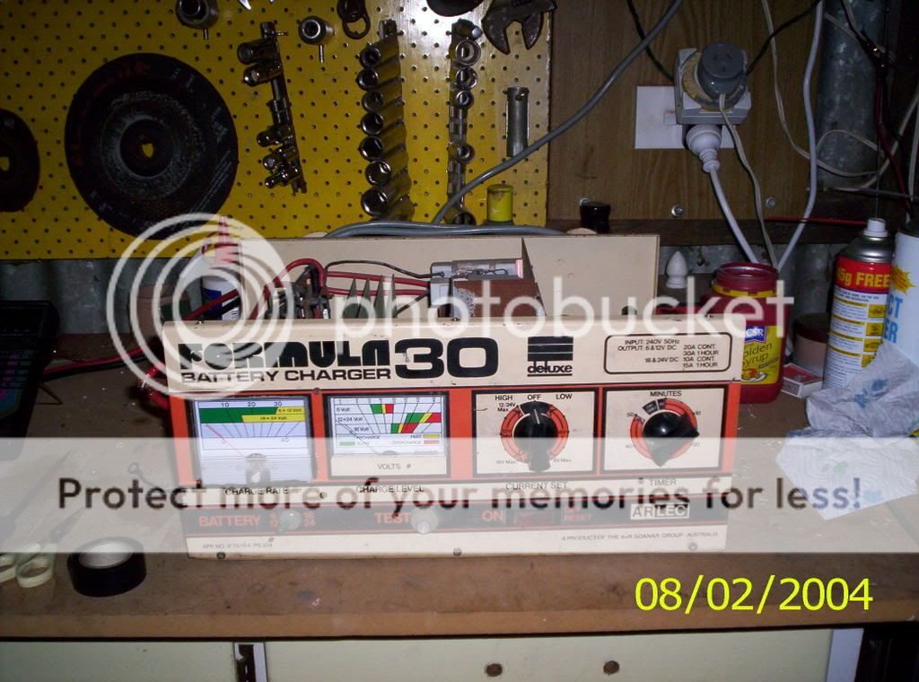
Fantastic
There's no load switch on my charger that's ok as you are working on many things
Question on the toasted trim pot for the Volts gauge as it checks out with the multi-meter to be OK except for the burnt resistor which I'm having trouble finding, is it a special 1 as it's a colour that i'm not familiar with??
Thanks again... ------------- I use to be confused but now I'm not so sure:)
Posted By: mag63
Date Posted: December 18, 2007 at 5:11 AM
Fired it up and amp gauge is no go and adjustment of the pot does nothing 
The charger also is putting out 14.55v so it is working and this volts reading is from my multi-meter as I had to disconnect the volt gauge (just hooking the jumper leads up to an flat battery 2volts in it sent the volts needle slamming over to the stop
Ideas
 ------------- I use to be confused but now I'm not so sure:)
Posted By: i am an idiot
Date Posted: December 18, 2007 at 7:40 AM
That shunt looks awfully short. The purpose of the shunt is to provide a voltage drop. Thus being an 80 amp bar you may need to file a few notches in it order to give it less current capacity. At one point you had said the meter was for the test function. I just assumed it was a stand alone tester. No worries the circuitry is still the same for this. Does it charge a battery? Use your meter and monitor the voltage at the battery. Do not leave it unattended. Just read battery voltage and then charge it a few minutes and unhook and check it again. There is a good chance that the volt meter is acting crazy because of the burnt potentiometer that controls it. Have you ever seen a fuse element that looks like a lightning bolt? That is the effect we are looking for on the shunt. It may need to be longer than it is. The longer it is the more voltage drop you can get across it. The amp meter is just measuring the voltage drop across the shunt. A little current, small voltage drop. A lot of current a lot of voltage drop. If the wires that go out the back are the wires that connect to the battery, the meter negative needs to be connected to the end of the shunt that is nearest the camera.
Posted By: mag63
Date Posted: December 18, 2007 at 7:20 PM
The shunt is 2 inches long.
Yes it is charging at 14.55volts.
ever seen a fuse element that looks like a lightning bolt? No don't think so.
Yes the wires that go out the back are the wires that connect to the battery.
The meter negative needs to be connected to the end of the shunt that is nearest the camera. Will check right now...
-------------
I use to be confused but now I'm not so sure:)
Posted By: i am an idiot
Date Posted: December 18, 2007 at 8:07 PM
Since you have the 80 amp bus bar you may need to make it look like this fuse. The thinner areas of metal will allow voltage drop. With it being only 2 inches long and having the 80 amp capacity 40 amps of current will not be enough to get any voltage drop. 
Posted By: mag63
Date Posted: December 18, 2007 at 8:07 PM
mag63] wrote:
The shunt is 2 3/4 inches long.
Yes it is charging at 14.55volts.
ever seen a fuse element that looks like a lightning bolt? No don't think so.
Yes the wires that go out the back are the wires that connect to the battery.
The meter negative needs to be connected to the end of the shunt that is nearest the camera. Will check right now...
And Yes that's how it's connected ------------- I use to be confused but now I'm not so sure:)
Posted By: mag63
Date Posted: December 18, 2007 at 8:17 PM
i am an idiot wrote:
Since you have the 80 amp bus bar you may need to make it look like this fuse. The thinner areas of metal will allow voltage drop. With it being only 2 inches long and having the 80 amp capacity 40 amps of current will not be enough to get any voltage drop.
Ha we both posted at the same time
ok will make a new shunt like the fuse shown..
It will be later today as I'm off to see the Doc
And we will win ------------- I use to be confused but now I'm not so sure:)
Posted By: mag63
Date Posted: December 19, 2007 at 7:13 AM
Woo hoo it's working!!!
Well the shunt is done and no improvement
What's going on I think to my self??
I remember I have an old Sanpet engine analyzer in the cupboard and it has it's own shunt as it can measure Amps straight from the alternator and lots of other things
So I hooked that up and got volts but still NO amps, then I worked it out that the battery I'm trying to charge is stuffed!!
Now with no battery to charge what can I use(thinking) ha got it, 2 spot lights and a globe for a test and got 12.58 v and 9 AMPS
Adjusted the pot and matched the chargers amp gauge to mine Fantastic!
I'll chase up a battery from a mate so I can do some real testing.
Next on the list can I get the same type of pot we used for the AMPS gauge to replace the fried trim pot on the Volts gauge???
Thanks 4 your support and for reading my book ------------- I use to be confused but now I'm not so sure:)
Posted By: i am an idiot
Date Posted: December 19, 2007 at 9:25 PM
Cool glad you got it working. You can try using the same pot. The one you already have. But I think you will need a 100K ohm pot for the voltage. Reason being with the shunt we were dealing with several hundredths of a volt. But I am not real sure, so try the pot you have and see how controllable it will be.
Posted By: mag63
Date Posted: December 19, 2007 at 9:38 PM
i am an idiot wrote:
Cool glad you got it working. You can try using the same pot. The one you already have. But I think you will need a 100K ohm pot for the voltage. Reason being with the shunt we were dealing with several hundredths of a volt. But I am not real sure, so try the pot you have and see how controllable it will be.
Hi thanks again
Am going to the electronic shop in a few mins so I'll get both the 1k and the 100k, their only $1.90 each
Will try it later this afternoon...
Thanks mate.. ------------- I use to be confused but now I'm not so sure:)
Posted By: mag63
Date Posted: December 20, 2007 at 6:38 AM
i am an idiot wrote:
Cool glad you got it working. You can try using the same pot. The one you already have. But I think you will need a 100K ohm pot for the voltage. Reason being with the shunt we were dealing with several hundredths of a volt. But I am not real sure, so try the pot you have and see how controllable it will be.
Mate you're a
No it didn't like the 1k so put the 100k pot in and the meter is within half a volt across the range compared to my digital multi-meter
Now just have to get a battery to charge and monitor the shunt and gauges
Out of curiosity what's involved replacing both analog gauges with 2 digit each digital displys
Also when do you stop for the Xmas break?? ------------- I use to be confused but now I'm not so sure:)
Posted By: i am an idiot
Date Posted: December 20, 2007 at 5:41 PM
Probably not much involved to change to digital. A digital amp meter will already be calibrated to the shunt that comes with it. A digital volt meter needs no calibration either. The only problem may be a steady 12 volt supply to power the electronics of the meters. A battery charger is usually noisy (electronically). They also put out a bit more than 12 volts. This may damage a solid state meter. You may have to get a 12 volt supply and mount it inside the charger to power the meters. Check current consumption of the meters to determine how much current the supply needs to provide. Break for Christmas? I guess Friday at about Noon. Then back to work on Wednesday.
Posted By: mag63
Date Posted: December 20, 2007 at 7:51 PM
i am an idiot wrote:
Probably not much involved to change to digital. A digital amp meter will already be calibrated to the shunt that comes with it. A digital volt meter needs no calibration either. The only problem may be a steady 12 volt supply to power the electronics of the meters. A battery charger is usually noisy (electronically). They also put out a bit more than 12 volts. This may damage a solid state meter. You may have to get a 12 volt supply and mount it inside the charger to power the meters. Check current consumption of the meters to determine how much current the supply needs to provide. Break for Christmas? I guess Friday at about Noon. Then back to work on Wednesday.
Hi, I wont change the meters just a thought. but it would look good
Well I have enjoyed doing this, both the chat and learning from someone who knows what their doing
If I don't catch you before your bit of time off work have a Good Christmas and Happy New Year!!
Cheers Mark 
and to the 12volt.com gang.. ------------- I use to be confused but now I'm not so sure:)
|