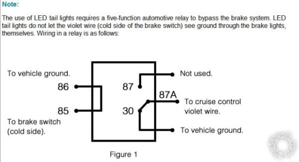
led third brake light relay
Printed From: the12volt.comForum Name: Cruise Controls
Forum Discription: Cruise Control Settings, Tach Signal, VSS PPM(Vehicle Speed Signal Pulses Per Mile), Vacuum, Brake, etc.
URL: https://www.the12volt.com/installbay/forum_posts.asp?tid=130800
Printed Date: February 22, 2026 at 5:46 AM
Topic: led third brake light relay
Posted By: bbstacker 7072
Subject: led third brake light relay
Date Posted: March 02, 2012 at 8:30 PM
The relay is energizing when I hit the brake and the tbl works. The problem arises when I connect the violet wire from the Rostra-immediately blows the stop light fuse. It appears I need someone to tell me how to connect the violet correctly. I have the chassis grounds under control and the relay coil is functioning. I just don't know why the fuse blows when connecting gd to gd. Thank you.
Replies:
Posted By: oldspark
Date Posted: March 02, 2012 at 9:50 PM
But why would a 3rd brake LED light be an issue - it should just be connected in parallel with the existing brake lights (whether +ve or GND switched).
If the existing brake lights are also LEDs, then any bulb-out alarm won't sense properly (until at least 2 of the 3 fail), but that shouldn't effect the cruise control.
As usual, it's always nice to see some authority using 86 to vehicle GND instead of 85.
[ Not that I care - I never use relays with internal (spike protection) diodes. But for those that do, it's a good way to "unprotect" the spike (with initial smoke) or blow the signal's fuse or circuit. (Maybe that's your problem? POST EDIT - no, it can't be...) ]
POST EDIT #2:
The diagram shows Violet being connected to GND, yet the installation instructions (250-1755_Form4838.pdf) under Appendix A. ELECTRICAL TESTING (A4 - Power Brake Circuit) states "IGNITION ON 12VDC ON VIOLET WIRE", and your diagram above states "do not let the violet wire see ground...", yet it is connecting violet to GND when the brake lights are on.
The latter suggests stop bulbs which are a low resistance to GND.
IMO #30 of the relay should be to (the brake circuit's) +12V - not to GND.
But why would LEDs be a issue if bulbs are not...?
Howie - where are you?
Posted By: bbstacker 7072
Date Posted: March 02, 2012 at 10:17 PM
Thanks for your help. I'm sure that airing all of this information will get me some interesting answers.
Posted By: oldspark
Date Posted: March 03, 2012 at 2:27 AM
But in this case, assuming brake bulbs, how the heck can adding a parallel LED array effect things? The added load is insignificant and electrically, the bulbs essentially short out the LEDs - ie, any rectification by the LEDs is bypassed via the bulbs. The resistance (& impedance) of the bulb/LED circuit will be indistinguishable from the bulbs alone (usually that is - ie, to within about 2%).
That's what attracted my reply. I wasn't even going to look at Rostra, but in case it was new confustigated thingamajiggy, I did. But it was a mere cruise control. (Yes - you mentioned "cruise", but to me that could have referred to audio or even a hair-blower.)
Then as I wrote my reply I got distracted into more & more detail. (Good! I reread your OP and diagram, and looked harder at the Rostra info. I often make the mistake of a quick read and total misunderstanding.)
And then I picked the two "don't ground the violet" info bits which IMO contradicted the relay wiring. (Obviously? Yes?)
Not that I am comfortable wiring violet (#30) direct to whatever +12V - you'd better wait for some confirmation first (though it "feels" pretty safe - if ground blows a fuse, the it is unlikely that +12V will do damage, but it might).
[ BTW - I added so much to my original reply that I deleted and reposted the modified reply. (For the reason I described in my earlier l-o-n-g 2nd reply to
And not that I know what the violet is, but if it's a brake sensing input, isn't it strange that EVERY user would have to add a relay? If the cold side of the switch is bulbs, then violet sees ground through a 4 Ohm resistance if it's two ~21W bulbs. If it's a LED array, the resistance is probably well above 200 Ohms (plus a voltage drop across the LEDs), so why would LEDs be a problem if bulbs aren't?
But that's where I'll play lazy and wait for others to explain. Howie will probably bedazzle me again with his awesome Unobtainium else Platinum knowledge and experience. Else someone else...
After all, it may not be a mere sensing circuit.
I was tempted to comment about companies that have +/- to a relay as 85/86 instead of the accepted norm of 86/85 and how that alone can make me suspicious. But if I'm right about the above - whether what LED impact?, else shouldn't #30 be to +12V? (and now, why the brake to get the unit to start operating?) - then I'd be real tempted to make a comment about stupid techs etc. I might then write what I've just written. But in case I'm wrong, I'll refrain. (ha bluddy ha!)
Oops, I digressed yet again... But funny how this reminds me of my recent "quality" and "un-controlled (document)" comments. Geez, I'm such an egotistical female canine.
Posted By: howie ll
Date Posted: March 03, 2012 at 4:32 AM
If the third brake light effects other things and I can't see how may I suggest a 1N4004 in line band towards the LED.
-------------
Amateurs assume, don't test and have problems; pros test first. I am not a free install service.
Read the installation manual, do a search here or online for your vehicle wiring before posting.
Posted By: oldspark
Date Posted: March 03, 2012 at 4:59 AM
Now, about certain professional technicians... (There's only one "o" in moron.)
I'd love to see a "please explain" (by the above tech)!
Posted By: howie ll
Date Posted: March 03, 2012 at 5:15 AM
Is the cruise violet it's brake light shut down feed?
If so it needs to see a pos for every vehicle I can think of except Lincoln Town Car/S type Jag, 98 on.
The way that relay is set up, bang.
My thought is that LEDs retain some capacitance so therefore I'd use the diode as a simple "anti-feedback"
I just tried some 12volt LEDs equivalent to 10watt wedge bulbs and dumped the power from my 35amp stabilised power supply,
bloody 13 seconds on full power till fade!
I think that's the reason.
-------------
Amateurs assume, don't test and have problems; pros test first. I am not a free install service.
Read the installation manual, do a search here or online for your vehicle wiring before posting.
Posted By: oldspark
Date Posted: March 03, 2012 at 6:51 AM
But the effect is the same - LEDs may cause Rostra input filter capacitance to decay too slowly.
But the that's only relevant if bulbs are replaced by LEDs - the bulbs will discharge any such capacitance quickly (at least 100-200 times faster than LEDs). Hence if LEDs are paralleled with bulbs, it should be a negligible effect.
No matter what, parallel bulbs should swamp the effect of LEDs. When unpowered, the bulbs are essentially a short circuit across the LED - eg, 8, 4 or 2 Ohms etc across (say) an 80 to 500 Ohm resistor (in series with a Zenor = equivalent LED series voltage).
And even then, if it is the "brake sensor" that disconnects the cruise control as soon as the brake is pressed (ie, +12V appears), then so what about the decay. (Unless the cruise can be re-enabled whist the brake is still applied, but surely no design is that stupid?)
Damn it - shall we inspect the full wiring or Rostra system?
I might be interested, but only after:
- it is determined that "normal and proper" connection to standard brake lights causes failure (or non-initiation);
- that addition of a LED across the stop lamp(s) causes failure...
- and that the addition of the relay has NOT been solely due to some advice, but in response to reality.
If only LEDs (no bulbs) is the only issue, I'd be curious why if the above are okay, but I'd put that down to an (IMO) crap design. But that assumes violet is the brake sensing to disengage the cruise.
[ I know the system gave problems with the addition of the 3rd (LED) brake light, but was that LED wired correctly OR does a 3rd bulb do the same. IE - the 3rd is not wired opposite to +12V switched brake lights (as if to be GND switched)? ]
[Caveat: It is late...]
An astute person recently wrote:Don't you hate when noobs are so right?
... I'm sure that airing all of this information will get me some interesting answers.
And they think they are embarrassed? Ha!
Posted By: howie ll
Date Posted: March 03, 2012 at 8:04 AM
The point our friend makes is to test.
Does the problem go if you take
1) The relay, or
2) The LED lamp out of the equation.
-------------
Amateurs assume, don't test and have problems; pros test first. I am not a free install service.
Read the installation manual, do a search here or online for your vehicle wiring before posting.
Posted By: bbstacker 7072
Date Posted: March 03, 2012 at 9:43 AM
Actually, I'm not using the relay and it is back as it was: led brake works, but cruise control doesn't. The instant I turn on the cruise control the abs/trac/vsc lights illuminate on the dash.
-------------
Think ya' used enough dynamite there, Butch?
Posted By: oldspark
Date Posted: March 03, 2012 at 11:02 AM
But I can safely agree/emphasise/reiterate what Howie II wrote - NEVER be embarrassed to ask. To quote one inspirational signature - "There is no such thing as a stupid question - only stupid answers." (I hope I got that right).
As to Howie II's succinct translation of my last reply, I'll blame tiredness. (That's bullsh - it's a normal reply for me, but why should I be embarrassed because of my stupid answer? LOL. And I did reiterate my interpretation...)
But for the benefit of my possible misunderstanding, do you still have the original brake bulbs as per "standard" with the LEDs? (Or have they been removed or substituted with LEDs?)
FYI - I am suspecting my stupidity and reckon I'll confirm it later (it's now 4AM Zulu) after a reread, else some new dawning (ie, sunrise - ha ha). (But embarrassed, no.)
Feel free to ignore this reply if redundant to too stupid.
I'm off to bed. Big day with Mother
 !!)
!!)
PS - links don't work (at least for newbies?). But a plain-text link should be ok.
Posted By: bbstacker 7072
Date Posted: March 03, 2012 at 11:47 AM
Hope you have a G'day with your Mother.
-------------
Think ya' used enough dynamite there, Butch?
Posted By: howie ll
Date Posted: March 03, 2012 at 12:01 PM
Adding LEDs should make no real difference to any circuit because their current drain is so small, don't forget also that a 12V LED will have a built in resister anyway.
-------------
Amateurs assume, don't test and have problems; pros test first. I am not a free install service.
Read the installation manual, do a search here or online for your vehicle wiring before posting.
Posted By: bbstacker 7072
Date Posted: March 03, 2012 at 1:10 PM
I appreciate from the bottom of my heart all of the replies. To me, Rostra needs to address this for me. And when I find out, I will most certainly post. I would think this to be a difficult endeavor for all of you anyway without a schematic of the Rostra unit to see where this violet wire goes and how it works..that's a Rostra concern.
I will try a few things thanks to you guys and wait for the tech to respond. Thanks to all of you. Bill
-------------
Think ya' used enough dynamite there, Butch?
Posted By: bbstacker 7072
Date Posted: March 03, 2012 at 3:06 PM
Anyway, thanks again for all of your inputs.
-------------
Think ya' used enough dynamite there, Butch?
Posted By: howie ll
Date Posted: March 03, 2012 at 4:16 PM
Result, more flaws, less customer services, silly fixes.
Two massive car security companies merged about 10 years ago.
Let's call them Alphaper and Betaford.
Alphaper had software programmed via an eprom writer which was ironic because the owner of Betaford invented the eprom, Betaford meanwhile used a software programm which was far superior.
The new owners got rid of Betaford's programmer which was a shame, it was far superior and guess what, ideally made for Win 98 and NT, it requires a serial port rather than USB and can't be upgraded.
But hey, that's business and f***k you once you've bought it.
-------------
Amateurs assume, don't test and have problems; pros test first. I am not a free install service.
Read the installation manual, do a search here or online for your vehicle wiring before posting.
Posted By: oldspark
Date Posted: March 03, 2012 at 5:18 PM
bbstacker 7072 wrote:
This is embarrassing to a degree...
Yes, indeed. But for Rostra!!
After 5 hours sleep I thought I'd return to find my misreading. (Yes - I read your "all LEDs" reply before bed.)
And your solution is what I would have directly suggested of I had realised all bulbs were REPLACED by LEDs - add back the bulbs or a bulb or smaller bulb (else maybe a high Wattage resistor).
And IMO that is so obvious yet we've been reading "if a LED is added" as opposed to bulbs replaced and LEDs substituted.
And what's this "do not let the violet wire see ground through the brake lights "?!
Yet then they show a relay that connects the violet wire directly to ground! Geez - will that cause a fuse blow whereas through bulbs may not?
In my first reply I aired doubts when I see certain things... FIGJAM again!
I should sue Rostra for causing undue stress OR wasting my valuable time AND they should discipline or educate their technician(s) - though it might have been a great tech having a D'oh Day or experience.
But I now view Rostra as just another "reputable company" that has gone bad. Don't trust their advice!
And Bill, you have nothing to be embarrassed about - that's clearly Rostra's ownership. Even I feel vindicated IF I did miss a LATER no bulbs, all LEDs statement - IMO my original reply said it all. (My writing is a different issue!)
This is akin to simple "hyper flashing" LED indicators - just add back the bulbs somewhere (else one 50W resistor, else two) or replace the flasher can or change its current sensing resistor, of just make your own 85cpm flasher (eg inverters or a 555 timer and (say) a 500mA or common 15A or 30A relay). That's a well known problem - not that it stops them trying to sell you expensive resistors (what a stupid waste!) or "special" flasher cans.
I'm glad this was solved before my further research!
IMO Rostra deserve a bluddy good rostral punch...
Meanwhile the commercial world continues our devolution.
PS - actually the webs is our devolution, commercial is our decline.
Posted By: bbstacker 7072
Date Posted: March 03, 2012 at 6:20 PM
I actually learned a little bit from all of you guys. Now, whether I'll remember it by morning is another story.
-------------
Think ya' used enough dynamite there, Butch?
Posted By: oldspark
Date Posted: March 04, 2012 at 4:02 AM
As for cutting jobs, I have generally been in favor of top down. That's how things work - if you cut the foundations, everything topples. Cut the demand before you burn the fields.
And ergo, that's what I reckon is happening today... cut and avoid training, cut wages, cut workers (without cutting workload else improving productivity), import "other" people, etc etc.
Skills are supposedly improving get managers and execs are generally finding LESS people under them. Shouldn't that ratio be increasing?
If that tech was undertrained, IMO that supports my rant above, or that management skills are dropping (didn't they know he was hopeless?)
If he was overworked or covering another area, ditto - why wasn't the workload dropped. (Don't worry, I have dealt with many that think increased productivity occurs through increase hours (LOL - it almost always drops!); productivity is a ratio (work out to hours in), it is not the same as output. (Did you know England's GDP INCREASED when they were reduced to a 3 day week circa 1980? Yet here they'd like us to work 6 days...)
As to people giving solutions they aren't knowledgeable in, I guess I merely lost a few hours, but you could have lost a life or a vehicle. Even qualified experts are sued for that.
(Though for the under-qualified, there are certain legal outs else mitigators...)
Posted By: howie ll
Date Posted: March 04, 2012 at 4:08 AM
And we all know about MY comments regarding competence don't we.
Pros will know exactly to whom Alphaper and Betaford refer.
And that story I quoted was true, I've heard it from both sides of the Atlantic.
-------------
Amateurs assume, don't test and have problems; pros test first. I am not a free install service.
Read the installation manual, do a search here or online for your vehicle wiring before posting.
Posted By: oldspark
Date Posted: March 04, 2012 at 5:56 PM
That doesn't mean success however. In the USA, suit of free advice is more likely to succeed. Here downunder, it would have to be more than "passive" advice (ie, its all in how you word it and what caveats/warnings are applicable).
But in this case, we'd be rewarded and Rostra sued.
Alas not being a pro I don't know the A & B case, but I'm sure I'll find out... But I know of so many similar examples, and my comments have been directed at a higher level (like web and human devolution) - but f.ex I just covered that on another forum regarding the new medical advice that reversed their previous (stupid, moronic, and obviously yet again untested) advice to isolate babies less than 12 months of age from peanuts for allergy reasons (not choking), and now the "withdrawal" of ADHD medication from minors (Der, how stupid was that?).
Not that I'm one to ramble and get off subject... (But since the OP issue is not solved and closed...)
Posted By: howie ll
Date Posted: March 05, 2012 at 12:10 AM
In my youth and I'm sure I'd have been a candidate, I was always in a rush and got bored quickly, the teachers simply sent me outside to play or up to the library for a read, but I suppose these days Health and Safety would say I wasn't being supervised correctly.
As in the previous post aren't we allowed a dash of common sense?
People/companies make mistakes, other people like the poster go on to sites like this for advice.
Hopefully the advice is correct, problems are solved and legal recourses aren't needed.
I don't know that much about them, 30 years ago in Florida I was installing 5 c/controls a week, here I now don't see any, all factory installed. But they appear a competent company, I would like to give them a chance to respond.
-------------
Amateurs assume, don't test and have problems; pros test first. I am not a free install service.
Read the installation manual, do a search here or online for your vehicle wiring before posting.
Posted By: oldspark
Date Posted: March 05, 2012 at 3:17 AM
However, it is with pleasure that I have just read through this entire thread and am happy that - until I specifically asked (and it was only the ambiguity of Bill's previous statement "The original filament bulb is 2 ohms" that caused me to seek confirmation), at no time was it evident that the original brake lights were also LEDs (and IMO it is obvious that I was talking about existing bulbs/filaments, ie, not LEDs - even though that should be irrelevant). The issue was merely the addition of a 3rd brake light which happened to be a LED.
But even then, it was clearly stated that the system worked with the existing brake lights (ie, LEDs), so why the problem with the 3rd? The existing LED lights obviously were sufficient to GND the violet. The 3rd LED could not have diminished that outcome (assuming it was connected in parallel to the existing brake lights - whether LEDs or bulbs).
Whilst that issue is a curiosity that I am unconcerned about (albeit interested in an answer), I cannot for the life of me understand the suggestion for that relay and its connection.
As I wrote, though Howie put it better, mistakes happen... IMO that can be understandable. (My sue or sack comments, though partly serious, were intended as jest.)
But I would like to see a response from Rostra if only to find what solution that relay is for, and if it is correct.
Ah, to 'L with it - I've just researched...
Bill's OP pic is verbatim from Rostra's FAQ, namely "Note: The use of LED tail lights requires a five-function automotive relay to bypass the brake system. LED tail lights do not let the violet wire (cold side of the brake switch) see ground through the brake lights, themselves. Wiring in a relay is as follows:...".
Not that its full context is clear, it seems to sit in the middle of unrelated info.
And FYI, what I call pins or terminals is what Rostra call "function". To me, a five function relay has more than 2 outputs and 2 states. (ha ha)
Another site adds a bit more intelligence:
NOTE: If running LED stop lights or some aftermarket blinker you will need a relay circuit that will supply a ground to the purple wire when stop lights are not energized to allow engagement.
Hence IMO the solution - the Rostra relay diagram is wrong. 85 & 87a go to GND. 86 (& 87) come from the brake switch (cold side) and 30 goes to violet/purple. Hence violet sees GND normally, and assuming a working hot brake switch, +12V when the brake is applied.
Note that the brake lights/LEDs can come from #30 or the brake switch (#86), and I have swapped Rostra's relay coil terminals (85 & 86) IAW normal convention. And 87 can come from +12V.
Of note from other sites:
"The wire going from the relay to the Rostra (Violet) MUST show 12 volts when the brake lights are on, and MUST show ground when the brake lights are off. If either state is not connected then the Rostra will not work correctly; either it will not engage, or worse, it will not disengage."
And from a 2007 install... "One word of caution though. The "experts" at Rostra kept giving me the wrong instructions for wiring the module to the brake lights, transmission & control unit. Once I disregarded their instructions and figured out how it should be wired, it worked fine."
I find it surprising that no one has yet corrected Rostra's diagram. Maybe people don't bother feeding back or complaining?
Or is it that Rostra has a quality issue with its publications and people are too exhausted? They speak of the difficulties installing Rostras and of Audiovox "taking over".
One line from one of Rostra's guides: "Best to add a 6 AWG wire between the Alternator & the engine cover frame to minimize the Electrical Interference as a precautionary step.". I wonder what part of the alternator readers might connect to the engine cover frame which is presumably GND (and should certainly NOT be made hot if it is isolated!)?
And speaking of hot, there were a few comments about +12V feeds getting hot. No wonder if they are shorting the brakelights' +12V to GND IAW the Rostra relay diagram. (What did I say about fire? Oh - I didn't - that was rolled into a concise "...you could have lost a life or a vehicle"... rats!)
Hmmm - 5 function; don't let PURPLE / violet see GND - just short it to GND via the relay instead; connect the alternator (+12V??) to the cover (GND??); ... and the rest I have already forgotten.
Funny - we used to have quality processes, business practices, proof readers, etc.
These budget and (lower level) staff cuts are getting interesting aren't they?
But my "non-professional" and free solution for all is merely to run a resistor (else a bulb) from violet/purple to GND. The resistor power required should not be high (that'd be a BAD design).
The Rostra CC should have that resistor internally - it is not a lamp checker, it only needs to know when brakes are applied. Hence a mere 4-pin (or 4 function) relay.
(And if designed for both +12V or GND switched brakes, that too is easily designed, else the least common (GND switched) should be the one to require extra fitting - namely the relay but with 86 to +12V and 85 to the downstream side of the brake switch.)
I wonder if someone or some site should be rewarded for pointing out these things BEFORE Rostra cause serious damage or injury?
Posted By: bbstacker 7072
Date Posted: March 05, 2012 at 8:59 AM
Up to this point I had never had one minute's problem with this unit.So, for me, lesson learned.
-------------
Think ya' used enough dynamite there, Butch?
Posted By: oldspark
Date Posted: March 05, 2012 at 4:19 PM
Not only did he NOT help you (he made things worse!), but he exposed Rostra to potential litigation.
I know he was trying to help, but it was wrong. Imagine if he had have lost his job and sent Rostra bankrupt. (How employable would he then be?) And he could also be added to the litigation, hence losing house etc etc.
And it still doesn't solve their seemingly incorrect FAQ diagram.
Nor the difficulties other customers will have as a result.
That diagram needs correction or at least further information - it doesn't even connect Violet to +12V as apparently required when the brakes are applied (ie, the CC won't disengage)!
And their accompanying text is wrong.
If I were Rostra, I'd specify the maximum resistance needed to GND and ditch the relay except as an alternative to a high-power resistor.
But if I were Rostra, that resistor would be inbuilt!! (For GND switched brakes, a simple inverting SPST 4-pin relay can be added.) Thus the majority would never need that FAQ etc.
Hence not only saving paper and customer resources, but modernising the unit for modern vehicles, and not losing lose further market share.
Bill, make Rostra aware of this issue, or at least warn your helper before it is too late.
Posted By: bbstacker 7072
Date Posted: March 05, 2012 at 6:30 PM
Right now I have a bulb in parallel with the third brake light. I have ordered a 50 watt 6 ohm resistor I am going to insert between violet and ground and then remove the other bulb. I already have everything mounted, I just kept blowing a brake fuse every time I hit the brake.
I hope with all the fuss I've created you won't ban me from the site. My goodness, you fellas sure ended up airing a lot of frustration. I have really enjoyed all of your posts. It is a pleasure to get in touch with people from different countries, and not bash each other for one reason or another. Definitely refreshing.
-------------
Think ya' used enough dynamite there, Butch?
Posted By: oldspark
Date Posted: March 05, 2012 at 9:05 PM
You may have saved the future world from repeating the same incorrect procedure.
You have stimulated discussion (as if I shouldn't be doing other things... uh-hum). [Oi - that's a compliment! I don't waste my time on (er, walkers, idiots, egotists...) fools. I may have spent (too?) much time on this, but it's been a positive. We including YOU collectively solved you problem; I have another example of devolution; and maybe we will save a life or injury or damage or law suits etc etc.]
You have been polite and attentive.
Crikey, neither of us have directed any sarcasm at you - not even the usually missed subtle narkasm. (Hey Bill, Congratulations!! Honorary Rookie, though we do attract the best here.)
The 50W resistor may not be needed, but if ordered...
That's where Rostra should specify the max Ohmage required (and hence calculate the Wattage = VxV/R - ie, 16V x 16V /R = around 250/R-Ohms Watts which should be reliable for 12V operation (which should rarely exceed 14.5V).
Alternatively it could be found by experimentation - probably using small bulbs and working upwards...
But beware of resistor heat when the brakes are applied or the brake switch is on for long periods! (Bulbs emanate slightly less heat - not that that means they are cooler. But they don't require special ordering and are easy to replace if they fail.)
And despite having a certain onus or obligation to contact Rostra about their potentially hazardous information, I probably won't. Though responsible enough to be under threat of litigation and criminal suits, I doubt that anyone will dare touch me.

Besides, there are several stakeholders that would fall before it gets to me... Though maybe a should email them as soon as I can get around to it after my higher hazard-saving priorities.
And you should not be blowing brake fuses every time you hit the brake because the Violet should only connect to GND when the brakes are off. When the brakes are on, violet should see +12V. Hence connect 87 to +12V and 87a to GND. Ignore Rostra's incorrect FAQ 87 & 87a connection!
bbstacker 7072 wrote:I thought you meant we aired YOUR frustration, but now I think I get it...
My goodness, you fellas sure ended up airing a lot of frustration.
But yes, I will air... And in my just posted reply on other thread I mentioned a colleague that "takes no prisoners. I never said that I do.... (LOL!)
And being into equality, that goes for you too! Not that I have even considered you as being close to that in this thread. (Friendly jest intended - please!; that's not even to be considered a hint or a warning.)
Bill, I look forward to helping you in anyway I can should you have future problems or questions. (Remember - there are no stupid or dumb questions...)
I may not see them because I'll be running like heck the other way...


And BTW - thanks for your appreciation. (And with apols for my airing and verbosity, though they should include some (important?) related stubs.)
And a belated welcome to the12volt!
PS (with some errors above corrected):
I forgot - your last about different countries and no bashing. In my experience, countries and cultures - or rather, people - are all similarly friendly and polite. (But hey - I wrote that we seem to attract the best!)
Some may sound brash and arrogant, but that is often their literal translation of their home language, else cultural differences. (EG - when offered biscuits/cookies here, take them. Don't be polite and decline - you won't be asked again because it is taken for granted that you take if and when you want to. In fact, rarely will Aussies even offer - that is taken for granted.)
But yes, there are bashers etc. Many IMO are merely misunderstandings or misreads - and they really frustrate me - there's a battle where none should exist; they actually agree with each other!
And then the bashers and egotists that are just the individuals you meet anytime, anywhere, etc. (Greetings <unmentionable relative>!)
I try to be polite and understanding else tolerant (...to the count of 3...) yet even I have battled - even after explaining whatever misread or other cause or difference, or me being too stupid to see the same.
That doesn't mean I'm naive, nor unprepared. I might count to 3 (or higher if their credits have built), but as to feeding prisoners... (LOL).
And I too have reversed or eaten humble pie - sometimes after a mere 2 counts, but sometimes from the front line.
Apols for that - it's just the rambling of one OldFart.
Posted By: oldspark
Date Posted: March 22, 2012 at 8:45 PM
Noting that I normally do not take on such tasks - if the person suffering the problem can't prioritise or be bothered, why should I? After all, I'm not going to get caught out by company's and peoples' bad advice - it's all the others that will waste time & money and repair damage etc.
(Though I'm not one to laugh at their loss and anguish. Instead I just suffer with the knowledge of all the crap info out their.)
However I have been using Rostra as an example of the type of bad information published and provided by so-called responsible and reputable sources. (As if well-meaning web posters aren't bad enough!)
Hence IMO due diligence should be exercised - they should be given the chance to respond and clarify, else be made aware and fix the problem.
It may save their future market too.
Posted By: bbstacker 7072
Date Posted: March 22, 2012 at 9:15 PM
The Rostra cruise system reads grounds before the brake switch is
pressed. This will allow the cruise control to set. Since LED lights
do not read ground when the brake switch is a the rest position, a 5
terminal relay is needed. Therefore, by using the attached wiring
diagram, it shows that we want to use the relay to apply ground to the
violet wire (brake negative). To energize the relay, 12 volts will be
provided by the brake switch when pressed and will release ground. The
resistor will not be needed.
Like you, I've had it.I just appreciate everyone's help and I'm glad Rostra wasn't the final say. I hooked that relay up just as they had it, and that fuse blew...that's all I know.
-------------
Think ya' used enough dynamite there, Butch?
Posted By: oldspark
Date Posted: March 23, 2012 at 2:37 AM
I honor your due diligence and effort.
I think I have concluded what idiots they now are, but I'd still like to be proven wrong (and make yet another justified claim for i am an idiot's name).
So they have a crap design (no internal pull-down resistor), still have contradictory info on their diagram, and still have IMO a crap solution - ie, a relay...?
Oh PLEASE, give me a brake (pun very intended!).
I still can't believe that I am correct. Surely I have missed something?
And whilst I accept that people miss the obvious - ie, re-connect a bulb else whatever (small?) resistor is required as a pull-down - that miss in combination with their other crap IMO beggars disbelief.
Surely I have missed something? (Yes, I know hat's a repeat.)
I think I will approach them - just for my own sanity if nothing else.
I just hope I don't get some "for safety..." explanation. I reckon then I'd hit the roof! (Or have I missed something there as well?)
Geez I hope I end up being severely apologetic for this...
But thanks again for your chase-up and reply. That at least has made me very happy.

Posted By: racerjames76
Date Posted: June 08, 2012 at 9:33 AM
Not to beat a dead horse but I may have another explanation on this topic. Think about the 12v signal coming from the brake switch. Full 12v looking for a path to ground. 2 systems independant of each other are looking for 12v when the brake is pressed, and ground when it is not being pressed.
When you have LED's hooked up that 12v goes to the LEDs and resistors, and then to ground. The point of course is after the electrical work of lighting the LEDs up and passing through the resistors has been done there isnt a full amperage 12v signal going to ground. That equals a working circuit.
By adding the relay in parallel you have provided an additional ground. Now as described earlier in this thread the fuse blowing is likely due to the feedback of 12v backwards across the relay coil. Another option would have been to install 2 diode isolated relays in series (cut the brake switched wire and feed it via one of the relays), then the other relay would operate the ground signal to the cruise's violet wire.
One source switches both relays, but each circuit is now separated completely.
Basically the brake signal wire 12v switched comes through 2 diodes (bands facing towards the relays) to pin 86 of both relays, and of course pins 85 both go to ground. The car side of the brake switch wire you cut will go to pin 30 of relay #1. Pin 87a of relay 1 goes to ground, and pin 87 of relay goes to 12v (can be the 12v source at the switch or fuse panel)
On relay #2 for the cruise you wire pin 30 to the violet wire from the rostra cruise, and pin 87a to ground, or following their diagram.
This method is very elaborate and may contain unneccessary parts, but it is 100% certain that the 2 circuits will work as intended completely independant of each other.
I think most of this was covered, but I thought these comments may help someone else in the future understand a little better.
The rostra cruise is looking for a solid ground on the violet wire, and in fact does not even need to see 12v at all. Just the loss of that ground when the brake is applied.
This is how I wire many standard transmission vehicles with the tach wire hooked up and 2 signals (clutch and brake) disengaging the ground from the violet wire. All in automatic mode. This way, the cruise sees the RPM jump when the clutch is pushed in and turns off the throttle, and as a fail safe when the clutch is fully engaged and the clutch switch is switched, it then turns off the ground to the violet wire. Multiple added fail safes.
Posted By: howie ll
Date Posted: June 08, 2012 at 9:36 AM
-------------
Amateurs assume, don't test and have problems; pros test first. I am not a free install service.
Read the installation manual, do a search here or online for your vehicle wiring before posting.
Posted By: racerjames76
Date Posted: June 08, 2012 at 10:07 AM
The other thing to consider here, is when you have the LED lights in place, the 12v signal is passing though a load, and a group of resistors. Consider that when the circuit is not energized (pedal not pressed) you do not have a full ground signal at the switch. The ground is also travelling through those same resistors. Grounds obviously do not "travel" but if you measured the resistance at the switch to a known ground it would be greater than true ground.
For example. You can find the ground wire after the LED lights and measure the voltage present when the pedal is being pushed, and you may very well see 12v, or slightly less. You have to remember it is at a milliamp rating by the time it reaches that grounding point. Still a short to ground but with no amperage behind it the circuit works correctly.
When a normal bulb is present you do not have a resistance to ground. You likely have full ground at the switch, or close to it. Whether or not that stays constant with a load applied is another matter, but it is something to be considered when talking about these types of issues. 
Posted By: oldspark
Date Posted: June 08, 2012 at 12:06 PM
Or paraphrased for lamps, what is the minimum wattage required - 42W, 21W, 10W, 5W, 2W, 250mW etc as used by lamps and LEDs.
For LEDs there is also the issue of their "zener-like" voltage drop.
But IMO this whole issue was pathetic for reasons including that the unit should (probably) have pulled itself down in the first place, and given that it didn't, the info provided by the manufacture is misleading and IMO incorrect (ie, that wire "should not" contact ground, yet they short it direct to ground via the relay!), and IMHO it's a stupid solution anyhow (ie, a relay - why not a resistor or lamp?).
Posted By: racerjames76
Date Posted: June 08, 2012 at 12:20 PM
All valid points there oldspark.
In no way do my statements reflect the opinions or views of Rostra, but it has been my experience that when you become a rostra dealer, your technicians become field engineers for their products.
I will leave it at that since I have nothing further to say about this company.
Posted By: howie ll
Date Posted: June 08, 2012 at 12:36 PM
As an aside, some years ago I installed a Clifford alarm R/S in a Renault Clio.
A couple of months later I hear the R/S isn't working.
On examination the only thing I can find is that the owner has installed LED rear lights.
Yes, not going to ground, reading about 3V, enough to inhabit the R/S through the brake light circuit. A parallel relay was required.
-------------
Amateurs assume, don't test and have problems; pros test first. I am not a free install service.
Read the installation manual, do a search here or online for your vehicle wiring before posting.
Posted By: oldspark
Date Posted: June 08, 2012 at 12:42 PM
Why no one else has managed to have the info corrected or clarified beats me. Maybe "field engineers" aren't clever enough, or maybe they don't bother once they figure out the solution. Or maybe Rostra ignore everyone... From my reading, this has been an issue for several years.
Though I can see arguments for both pull-up & pull-down "defaults", I cannot understand their IMO pathetic info and solution.
Maybe they lack the English skills for a user-friendly else technical explanation, though it seems to me to be a lack of design skill.
Incidentally, I haven't yet written to Rostra - a PC-crash issue killed that for a while. I may still do it, though it may also become yet another of my "mere observations". (Sometimes I don't hand out the rope - I just let fate take its course.)
Posted By: racerjames76
Date Posted: June 08, 2012 at 1:04 PM
howie ll wrote:
I just wonder if racerjames is the new me?
I am but a mouse among men here! 
Not to drag this thread out into a rostra bash fest, but i recently did a data cruise in an 05 F150. In the instructions, it clearly stated to run a VSS or equivalent (forget what they called it) out to the ECM on the passenger side of the firewall. Well with that wire hooked up the cruise would not engage. Remember I followed the directions perfectly. I call tech support and the guy gives me an attitude like I am supposed to know that the wire at the ECM is not needed and is creating noise the cruise can not understand.
Now how exactly would a field tech know that unless stated in the manual?
The unit ended up causing all kinds of issues in that truck, to which some of them could have been blamed on the engine tuner module located on the dash. Think bullydog or equivalent (not diesel). Something like it was preveting the computer from seeing cam sensors and a whole list of other things. The dealer removed both items at the same time so we don't know which was the real problem. Anyways I need to stop bashing Rostra..I get paid handsomely for installing and engineering their products!
Posted By: howie ll
Date Posted: June 08, 2012 at 1:52 PM
-------------
Amateurs assume, don't test and have problems; pros test first. I am not a free install service.
Read the installation manual, do a search here or online for your vehicle wiring before posting.
Posted By: oldspark
Date Posted: June 08, 2012 at 7:57 PM
racerjames76 wrote:
I am but a mouse among men here!
And I'm the rat!
I now understand RacerJames' reply about becoming field engineers a bit better. (Dare I say "funny" how the chiefs blame the Indians? It's part of what I call Karpinism or "The Karpin Club", or maybe what Drucker, Covey, et al (self proclaimed "walkers") call "yes-men gone wrong"...)
My "bashing" is directed at modern info systems and education. Crap begets crap. And subject to its exponential growth, the number that know the "correct" answers are ever diminishing. So far we are still surviving despite the overwhelming majority of bad info, but I wonder how long for...
That techs & readers regurgitate incorrect reference material is to be expected. However with the dumbing down of so many skills, it's as if no one can "think" their way to something better.
Regular readers will recognise my generic socio-fiscal comments above.
How that applies to Rostra is IMO yet to be seen.
I expect however either to be ignored or met with aggression, else simply not understood (IMO as with OP bbstacker) - unless they're golfing down their local Karpin Klub... LOL.
Posted By: bbstacker 7072
Date Posted: June 08, 2012 at 10:01 PM
I did indeed contact Rostra after all of this discussion and I got basically the same reply. Surely, others had contacted them on this. I hooked it up exactly as was published on their site and I blew a fuse every time. i hope I'm not getting everyone all fired up again, I just wanted to use this as a way to say hello to all of you fellas.
Right now I just have a regular bulb in parallel with the led array and it's working fine. But I would like to try another way that might be a little more professional and there were definitely a few listed here.
Thanks again for all of your help.
-------------
Think ya' used enough dynamite there, Butch?
Posted By: oldspark
Date Posted: June 09, 2012 at 12:12 AM
I forgot this was all YOUR fault!
Just kidding!!
I do dislike wasting MY time, but no poster here has done that. It is Rostra that has caused that. (That's subject to my own direct confirmation, but as bbstacker repeated above, it seems almost conclusive...)
The "more professional" solution is a resistor in parallel with the LEDs.
I doubt that a 12Ω 25W would be required (~equivalent to a 21W bulb) - hopefully something like above 220Ω (and hence 1W or less) would suffice.
But that is where Rostra should be able to supply and answer.
If they can't specify what minimum resistance is required to "pull down" their input, I'd wonder who the heck is doing their design and supplying their tech information because they certainly have no clue.
As to how a company can remain ignorant of such a long standing problem...
Oh well, that's Enron, Mistral, Karpin...
Maybe they know the are already out of business?
It's probably just a matter of time until Rostra are sued for damage or injury.
If it's after I contact them, I reckon I can assure it will be a criminal issue.
Posted By: racerjames76
Date Posted: June 09, 2012 at 8:11 AM
The generic cruise's are 70's, if not earlier, technology. I am almost positive a different company or at least a different division of Rostra builds the data cruise's. I thoroughly enjoyed reading and replying to this thread.
I agree the easiest fix is a resistor as you described oldspark.
I am not one to take the easy route often! Much to my own demise most of the time 
Posted By: howie ll
Date Posted: June 09, 2012 at 8:37 AM
I just purchased a Rover 75 Tourer 'cause it was big cheap quiet and power everything (Google it, never sold in the US).
This was simply put a front wheel drive BMW 5 Series BUT:-
Different colour wiring looms, the multifunction module was a US Lear instead of Siemens and it had a crazy keyless entry system where the factory fob deadlocks and has priority unlock.
What a joy overcoming this, my old Cliff gives me deadlock on arm, regular lock on run, even finding out how to dump the (7) domelights on alarm lock the original fob (with all of 2metres range) did it through the multifunction module. And yes the heating/AC strays in the position you left it in last when you activate the R/S.
-------------
Amateurs assume, don't test and have problems; pros test first. I am not a free install service.
Read the installation manual, do a search here or online for your vehicle wiring before posting.
Posted By: racerjames76
Date Posted: June 09, 2012 at 9:30 AM
howie ll wrote:
Yes but I bet you feel the joy when you think of a solution that works, especially one that no one else has thought of.
That warrants a new signature...
-------------
To master and control electricity is perfection. *evil laugh*
Posted By: howie ll
Date Posted: June 09, 2012 at 9:35 AM
-------------
Amateurs assume, don't test and have problems; pros test first. I am not a free install service.
Read the installation manual, do a search here or online for your vehicle wiring before posting.
Posted By: oldspark
Date Posted: February 27, 2013 at 4:55 PM
The led backup lights and remote start thread caused me to review this thread. As stated on this page 2 by me, I stuffed up in my first reply in this thread, namely:
Note my mistake in my first reply to bbstacker's thread. I state that Rostra say "do not let the violet wire see ground...". In fact the full line is "LEDs do not let the violet wire see ground...".
I have forgotten why the Rostra blew fuses. I'm certain it was a direct shorting of brake circuits etc to GND, but now I wonder if it was (also?) from using spike protected relays with internal diodes and following Rostra's inverted #86 to GND and #85 from the +12V switch. (It must be the other way if relays have internal spike protecting diodes. Their wiring will blow fuses or the internal diode.]
Incidentally, chasing this up with Rostra has been on my mind since ... last year..., but, you know...
And of course blaming Rostra now depends on what I find, or re-find.
Not that I may get to review this issue till, um, next year. ....Or next millennium...
Cheers.
Posted By: howie ll
Date Posted: February 27, 2013 at 6:07 PM
Shame on you whoever did those relay diagrams, excellent tutorial but the terminal 86 and 86 inversion?
If ISO states that 86 is POS and EVERY car manufacturer agrees then I'll follow that.
-------------
Amateurs assume, don't test and have problems; pros test first. I am not a free install service.
Read the installation manual, do a search here or online for your vehicle wiring before posting.
Posted By: oldspark
Date Posted: February 27, 2013 at 6:54 PM
Deviations to that shall be accompanied by a note to ensure internal-diode relays are NOT used.
Many know the objection I have always had to such relays. Instead I prefer to add my own diode when required.
In part that's because I question why should a spend extra for a relay or if a particular relay blows. As you wrote recently, manufacturers include spark sensing and other circuitry in choke & fuel pump relays or other relays to make more money. If either part fails, you replace both. (And what better way to fail a circuit than by including it in the relay....?)
And adding my own suppression diode means I control polarities - ie, I choose which polarity to wire, and the diode is usually then part of the wiring rather than the relay so that such fuse- and diode-blowing situations can't occur.
I suspect manufacturers now agree with me, at least on diode protection. They now seem to be rare and resistors used instead.
And I don't think the newer ISO micro relays have a similar polarity convention.
Or if the do, they don't have internal diodes.
If they do have internal diodes, then that will be a great money spinner - newer vehicle fuseboxes often have one-piece metal rails that connect to either micro relay coil terminal (eg, Delphi) much like my relay wiring.
I still think however that the Rostra issue was more than their 85 & 86 transposal.
But seeing such errors make me question the abilities of such manufacturers etc.
Not that I never knew of that convention until after I started contributing to the12volt. But I had no need to - I would merely follow the relay body diagram (which showed if there was an internal diode). And I never specified dioded relays to others (I'd stress to use plain relays and add external diodes or resistors etc) though I'd never specify pin numbers anyhow since my diagrams etc were generic for any type of relay (they were not the "physical" or "wiring" types as generally used on the12volt).
Posted By: oldspark
Date Posted: February 28, 2013 at 1:26 AM
I've just returned from the wreckers and have an internal diode micro relay. Form that I assume their convention is #1 is +ve & #2 is negative [with 3 being common (30), 5 NO (87) & 4 NC (87a)].
Maybe I should recheck what I said about their coil terminals being "randomly" hard wired to GND or +12V...?