temperature displays
Printed From: the12volt.com
Forum Name: Lights, Neon, LEDs, HIDs
Forum Discription: Under Car Lighting, Strobe Lights, Fog Lights, Headlights, HIDs, DRL, Tail Lights, Brake Lights, Dashboard Lights, WigWag, etc.
URL: https://www.the12volt.com/installbay/forum_posts.asp?tid=112440
Printed Date: March 09, 2026 at 8:38 PM
Topic: temperature displays
Posted By: bigjohnny
Subject: temperature displays
Date Posted: March 17, 2009 at 7:23 AM
Im not sure if this is the right place to put this, but this seems like the "electronics" section, sorry if its in the wrong place.
Are there any circuits available that will read and display temps for certain probes on an LCD screen, perhaps something a little nicer than a basic clock looking screen.
I want to put a couple of temp probes in my trunk to keep track of temps, but I don't know how I would display it.
I also want to be able to control a device if the temps get too low (a heater).
Does anything like this exist? could I build one? (yes I could BUILD one.... design one, no)
Replies:
Posted By: KPierson
Date Posted: March 17, 2009 at 8:50 AM
Dakota Digital has some temperature probes / displays. If you can get the probe and display installed I wouldn't think it would take too much to trigger a relay if the temp gets too low. I looked in to doing something like this years ago but never went through with it. I was going to use a simple RTD and a 2x20 display. ------------- Kevin Pierson
Posted By: bigjohnny
Date Posted: March 17, 2009 at 5:53 PM
This is something I want to look into, our winters are cold, and I want to mount a little heater in my trunk so I can keep an eye on temps in there (humidity would be the icing). I dont want to fire up my system when its been sitting overnight in -25C weather.
If I had a heater in there, it could be turned on to get the temps in the trunk up to something a little more acceptable.
I was also considering using a peltier to keep my amps cool(either directly on the heatsinks, or making a chiller of sorts like those electric coolers) but I just don't think thats an option... not one worth doing anyway....... gonna have to just go with a ton of fans :D
Posted By: KPierson
Date Posted: March 18, 2009 at 5:53 AM
What about a heater with a built in thermostat? You could power it off the ignition and possibly even set up a "low temp" light off of it.
-------------
Kevin Pierson
Posted By: bigjohnny
Date Posted: March 18, 2009 at 6:48 AM
thats not a bad idea, but I would still like to see what the actual temps are.
I'm a very visual person, and I like to be in control of my machines.
What I'm looking for I guess is some form of temperature controller.
I see an ad above for custom electronic design.... I wonder if they can design something for me..... more importantly, what would it cost lol.
Posted By: KPierson
Date Posted: March 18, 2009 at 12:30 PM
They make all types of temperature controllers and displays - places like www.omega.com would be a good start. These are more industrial devices though, so you'll need to make sure they'll work down to 12vdc. ------------- Kevin Pierson
Posted By: bigjohnny
Date Posted: March 19, 2009 at 5:01 PM
I'm kind of lost there, I'm not entirely sure what it is that I'm looking for, so it makes it a little hard to find there.
Also from what I've seen of their controllers/displays, they are the big blocky ugly LCD displays..... I want to make my car look like its from the future, not back to the future ;)
...... although I do need more jigawatts......1.21 of them.
Posted By: bigjohnny
Date Posted: March 26, 2009 at 6:49 AM
I've found this, https://www.geocities.com/ CapeCanaveral/Launchpad /3632/scriptherm/scriptherm.htm It might work, But I can't exactly follow the diagram, its a little bit beyond me ..... on top of that, the biggest problem is where would i get a PCB for this?
Posted By: bigjohnny
Date Posted: March 26, 2009 at 10:04 PM
ok, here is a slightly better one, or more ready to go anyway.
https://..ca/Digital-Thermometer -Temperature-Meter -Gauge-C-F-PC-MOD _W0QQitemZ250396214426Q QcmdZViewItemQQptZ Weather_Devices? hash= item250396214426 &_trksid= p4634.c0 .m14.l1262
But would there be some way to tap into it to activate a heater when the temp is below 10C?
Posted By: KPierson
Date Posted: March 26, 2009 at 10:11 PM
For the price it's worth a try. I would say it is safe to assume the signal coming back on the probe is a voltage, so I would think it could be modified to work with other applications.
-------------
Kevin Pierson
Posted By: bigjohnny
Date Posted: March 27, 2009 at 9:43 PM
the real issue is the set-point. how would I make the temp display activate something at a specified temp? thats the tricky one since it has no options for that kind of thing... it just displays temp. so there is no way to signal when something should be turned on or off.
Posted By: KPierson
Date Posted: March 27, 2009 at 10:38 PM
It depends on how it works. If the temp probe is a simple voltlage coming back that represents temperature all you would need is an op amp wired in to the temp probe to make your own set point. There is a thread on this site about adding a low gas indicator light, it has the circuit diagram that should work with this.
-------------
Kevin Pierson
Posted By: bigjohnny
Date Posted: March 28, 2009 at 7:54 AM
OHHHHH I see what your saying, the probe would send back a variable voltage based on temp. Find what the voltage is at the temp I want to activate the heater, and add an op amp to trigger a relay etc.
I get the gist of it now, I just need to figure out if the probe sends out voltage, and how to do it all :)
How would other probes work? The guy selling these is asian, and I don't think he reads english very well, So I want to be clear about what I'm asking him (IE if the probe sends back a voltage)
Posted By: bigjohnny
Date Posted: April 05, 2009 at 10:09 AM
yes these units use a thermistor for the sensor.
I ordered one. $12 CAD free shipping.....pretty good deal, except its 5v, so I will need to tap into a 5v power source, or use a resistor or something.
Posted By: KPierson
Date Posted: April 05, 2009 at 12:39 PM
A resistor won't help you, you will need a 7805 voltage regulator. ------------- Kevin Pierson
Posted By: bigjohnny
Date Posted: April 05, 2009 at 7:07 PM
really how come? this what I need?? https://www.radioshack .com/product/index .jsp?productid=2062599
What kind of op amp would I need to trigger a relay at around 5 degrees celsius? or do I need to take a voltage reading to determine that?
Posted By: bigjohnny
Date Posted: April 07, 2009 at 8:50 PM
On another note, if i wanted to add more sensors, would it be as easy as connecting them to a board, having them share the single input, and simply switching between which sensor is actively connected to the display? (if that made sense)
Posted By: KPierson
Date Posted: April 07, 2009 at 10:09 PM
Yeah, that should work.
-------------
Kevin Pierson
Posted By: bigjohnny
Date Posted: April 22, 2009 at 9:44 PM
were you saying "that would work" for both questions?
Posted By: KPierson
Date Posted: April 22, 2009 at 9:54 PM
No, it was just an answer to your last question, I didn't see your first question. Resistors don't drop voltage - they resist current. To convert votlage from one place to another you need a regulator (most common way, but there are others). The part you linked to will work great. To set the relay at 5 degrees you will need to measure the voltage at 5 degrees and then build the op amp circuit that compares voltages. ------------- Kevin Pierson
Posted By: bigjohnny
Date Posted: April 22, 2009 at 10:09 PM
ok.... also, how do I measure the voltage of the thermistor?
When I set my DMM to DC and 2v, It stays around .020 -.027
Posted By: KPierson
Date Posted: April 22, 2009 at 10:12 PM
Does that voltage change when the thermistor changes?
-------------
Kevin Pierson
Posted By: bigjohnny
Date Posted: April 23, 2009 at 6:31 AM
it does change, but it doesn't seem to be inline with the display.
at about 30C, the voltage jumps around .020 and .024 when the temp is about 26C, its floating around .020 and .026
I cant help but feel i'm doing something wrong.
How should the DMM be set? AC? DC? (I used DC)
Posted By: KPierson
Date Posted: April 23, 2009 at 8:50 AM
With that low of a voltage reading it almost seems like your probe is a thermocouple and not a thermistor. Thermocouples work down in the mV range. The voltage coming back is DC and should be measured against the ground of the unit. ------------- Kevin Pierson
Posted By: bigjohnny
Date Posted: April 24, 2009 at 7:01 AM
measured against the ground, what precisely does that mean?
Posted By: KPierson
Date Posted: April 24, 2009 at 8:21 AM
black probe to ground, red probe to sensor input. How many wires come back on the sensor wire? ------------- Kevin Pierson
Posted By: bigjohnny
Date Posted: April 24, 2009 at 4:47 PM
just two, black and red. so I had red to red and black to black.
Posted By: KPierson
Date Posted: April 24, 2009 at 4:57 PM
I would probe from the units ground to the two wires and see if you get a voltage back on either one of them.
-------------
Kevin Pierson
Posted By: bigjohnny
Date Posted: April 24, 2009 at 7:55 PM
so that would be the black wire that provides ground to the unit itself right? the black wire(gound) on the molex thats powering the entire thing?
This thing is a pain to take apart, its really weird. its like florescent display or something, and nothing will show up on the screen unless all the pieces are actually pushed together with some degree of force.
Anyway if thats the correct way to test it, I'll do that.
Should I use the 2v setting? or something else?
Posted By: bigjohnny
Date Posted: June 10, 2009 at 7:07 PM
Ok, back to this, I still haven't purchased replacement displays since I burned the other two out, but I need to figure out how I'm going to do this as I have now almost completed my bezel with the holes for the displays in place of the vent.
Here is the display all taken apart. Now how the hell does this thing work?? The LCD display has only the gauge line on it (GREEN/ YELLOW/red) and NO physical connection to the circuit board.
As you can see it consists of the screen with a sheet of paper on the back, then a small "reflector" of sorts(the clear plastic piece with yellow wires) that has a small LED on the side, and does nothing more than light up. There is a piece of white paper to act as a reflector for the light, and then a small frame, and the circuit board sites on top of that.
there is NO DISPLAY AT ALL if this is not squished together. if it isn't squeezed tightly together, the displays simply lights up, there are no numbers or anything other than the gauge line until you press it together.
Here is the board, and the part that I fried. (The circled part with the bubble on it)


This is the unit at each step of assembly.


so how can we figure out what voltage is coming back from the temp probe (the long RED / black wires) and wire it up to an op-amp to control a relay?
Posted By: i am an idiot
Date Posted: June 10, 2009 at 7:43 PM
I was going to find you a part number for the transistor, but then I noticed the resistor above and to the left a bit. Then I noticed the trace from the resistor to the microprocessor has heated up. The microprocessor is probably toast.
Posted By: KPierson
Date Posted: June 10, 2009 at 8:51 PM
If you look at all the "fingers" under the RHOS type that is most likely where the screen makes a connection with the board. They use a "zebra" strip thats basically a conductive cushion to make the connection between screens and boards. If you don't look at the little strip closely you would never guess that it is conductive. This is also why if you don't put enough pressure on it the actual display doesn't work. The only thing is is that I never saw a zebra strip in any of the pictures! How are you burning these things up? ------------- Kevin Pierson
Posted By: i am an idiot
Date Posted: June 10, 2009 at 8:59 PM
Bottom right of the second picture he posted. It is black in color instead of the conventional grey.
Posted By: KPierson
Date Posted: June 10, 2009 at 9:08 PM
i am an idiot wrote:
Bottom right of the second picture he posted. It is black in color instead of the conventional grey.
Wow, good eye. I didn't scroll over and it was completely cut off my screen! I think you can also see it in the first picture too, it's just really small and hard to make out. ------------- Kevin Pierson
Posted By: bigjohnny
Date Posted: June 12, 2009 at 8:50 PM
I wondered if that was how it was done, thats neat I've never seen that before.
How do I keep burning them out? I had them wired backwards, they are polarity sensitive... I won't make that mistake again.
seeing the unit now, how can I determine if this can control a relay at a certain temp? how would I measure the voltage from the thermistor?
Posted By: bigjohnny
Date Posted: July 09, 2009 at 9:15 PM
Alrighty, so coming back to this now, I've got my new meters, I've measured the voltage from the theristor across the thermistor positive, and the main power negative, this seemed to have a more definitive effect over the last measurement.
I wrapped up the probe in an ice pack and observed the voltage going up as temp went down.
At 0C the voltage was 0.032v - 0.035 (measured using my meters 2v DC setting)
so what kind of op amp would I need to trigger a relay when the voltage hits 0.030?
Posted By: KPierson
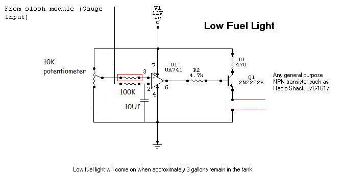
Date Posted: July 10, 2009 at 6:09 AM
tid=105885&KW=low+fuel There is the op amp circuit that I am an idiot posted. For such a low voltage you may need to modify the 10K pot on pin 3 of the op amp to include a 2nd resistor in series with the pot (creating a voltage divider and allowing you to focus the pot on a smaller voltage range). I would also recomend getting a pot with as many turns as possible (>20). That will allow you to dial in the voltage with more precision. ------------- Kevin Pierson
Posted By: bigjohnny
Date Posted: July 10, 2009 at 6:51 AM
hey thanks, I could not find that for the life of me.
as I understand that the "gauge input" would be the positive lead from the probe, and the "LED" leads would be the ones that trigger the relay?
what value should I use for the 2nd resistor?
it would be like this ? (stuff added is in red)
I should also mention that I'm not very well versed with wiring diagrams, I understand it to a point, but some of the symbolbs i'm unsure of, or certain connections. like the 12V +V?? The probe would be connected to the slosh module input and the 12V +V would be 12V positive power?
Posted By: i am an idiot
Date Posted: July 10, 2009 at 7:31 AM
R1 is to limit the current to the LED. If driving a relay, it needs to be eliminated. You will need a different transistor. With the voltage you need it to turn on at, it is going to be really hard to set with the 100K pot. We will have to add a resistor at the top ot the potentiometer and maybe use a 470 ohm potentiometer. This will eliminate the extra resistor you added and give you much more control. I will get you a resistor value tonight. I have a diagram that uses a 7805 regulator to give a more stable control. I will modify it tonight also.
Posted By: KPierson
Date Posted: July 10, 2009 at 8:30 AM
Why would the transistor need to be replaced? I'm not familiar with the 2n2222 but I always thought itw as a fairly decent general purpose transistor (it seems to be the most common transistor used on internet diagrams). If the 2n2222 doesn't work I know a 2n3904 will work. The base resistor, R2, will have to be dropped quite a bit, as well, probably down to 470 ohms if I had to guess. ------------- Kevin Pierson
Posted By: bigjohnny
Date Posted: July 10, 2009 at 11:33 AM
I have a 7805 circuit built already to power the displays. it also has the caps to smooth out spikes. Done as provided by the fine people here. :) So I already have that I can tap into, It will be powering both temp displays, and could probably power this new circuit I need to build. I could not for the life of me ever figure out what parts I need to do what I want here, but if you guys know the parts needed I can buy'em and build it. this is really low voltage too, 0.030v for 0*C, and around 0.017v for 24*c
Posted By: bigjohnny
Date Posted: July 10, 2009 at 7:57 PM
sort of off topic, but are there any decent programs to design circuit boards/PCBs, and/or make wiring diagrams easily?
I think I used something called smartdraw in the past when I was dabbling with electronics. anything better/more useful around?
Posted By: bigjohnny
Date Posted: July 11, 2009 at 10:07 AM
no word on resistor/transistor values yet? I would like to go and pickup the parts today so I can make this as I'm pretty well finished the dash beze, to mount the stuff, I wanna get it all back in my car.
Posted By: i am an idiot
Date Posted: July 11, 2009 at 9:04 PM
When the voltage on pin 2 goes below the voltage on pin 3, the relay will energize. I did not go back and see how your probe reacts to temp, nor did I go back and see if it is to trigger a fan at a high temp or a heater at low temp. If it is backwards this way, simply reverse pins 2 and 3 of the diagram. 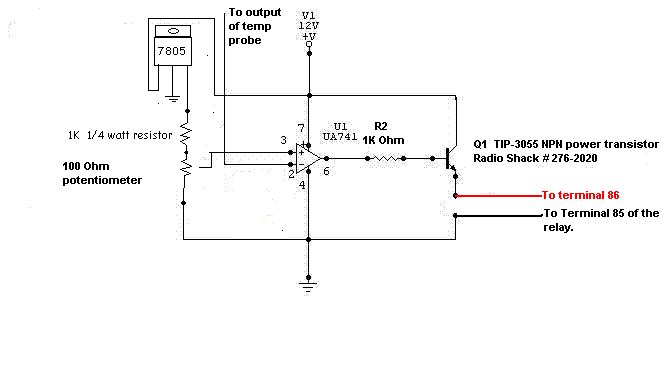
Posted By: bigjohnny
Date Posted: July 12, 2009 at 7:10 AM
Thanks, It will trigger a heater at low temp. The probe reacts like a thermistor...temp goes up, resistance goes up, voltage goes down.
it's all very tiny voltage, 24*C shows a voltage of 0.017v
anyway let me make sure I've got this straight V1 is what?? is that what connects back to the circuit board where the probe red wire was, and "output of temp probe" is where the red wire from the probe connects?
So is this what I would be doing?
Posted By: i am an idiot
Date Posted: July 12, 2009 at 7:27 AM
The non positive wire of the probe should be already connected to ground inside the Temp Display. Check that for me. V1 is 12 volts to supply power to the circuit and power the relay. Do not run 12 volts back into the display. If I remember correctly, that is what this thread was started by. You have to leave the probe connected to the display. Simply attach the wire from this circuit along with the probe wire. 
Posted By: bigjohnny
Date Posted: July 12, 2009 at 7:36 AM
I'll double check and get back about the probe grounding in about 20 mins, but I don't think it is(I could be wrong) because in order to get an actual reading of probe voltage I had to measure the probe red against the displays ground.
When I tested both probe wires, the voltage didn't do anything..... the value is posted on page one I think, but it did nothing as temp changed.
now that 7805, it produces 5v? and does what?
I've already built a 7805 circuit to power the two displays, and my volt/amp meters, could I use that existing circuit to power this instead of the 7805 in the diagram, or is that needed for this circuit specifically?
Posted By: bigjohnny
Date Posted: July 12, 2009 at 7:50 AM
I am unable to determine if the probe ground is connected directly to the display ground, but here is a pic of the circuit board, as mentioned above, I don't think it is directly connected.

Posted By: i am an idiot
Date Posted: July 12, 2009 at 7:51 AM
You can use your present regulators. There is minimal current draw from this circuit. No need to check the probe. If the voltage is changing when referenced to actual ground. This is what we need.
Posted By: i am an idiot
Date Posted: July 12, 2009 at 8:07 AM
I changed the value of the resistor that connects to the 7805. With the 1K resistor the control would be from 0 to (.)49 volts. With the 10K resistor you will have much better control. 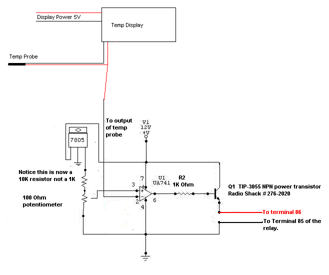
Posted By: bigjohnny
Date Posted: July 12, 2009 at 8:13 AM
my existing regulator circuit has only pos/neg output.... I would need to tap into the "in" pin on that circuit connecting it to Q1?
you know, it's probably just easier if I buy another 7805 and just build this as it is.... no need to make it more complicated.
any suggestions on a relay? or will any relay rated for my purposes do the job?
Posted By: i am an idiot
Date Posted: July 12, 2009 at 8:21 AM
I was assuming you were going to use a standard automotive relay. If you are using a smaller relay, we may be able to use a smaller transistor. As the diagram sits, you can use pretty much any relay with a 12 volt coil. If you are using a smaller relay, let me know the resistance of the coil and we may be able to use a smaller transistor as well. You do not have to connect to the input pin of the regulator. You can connect it to the source that is feeding the input pin of the regulators.
Posted By: bigjohnny
Date Posted: July 12, 2009 at 8:53 AM
I was going to use any relay I could find that would work basically... maybe not standard automotive since I was gonna take a look around my dads garage.....he's got tons of stuff like that.
a heater would tend to draw a lot of current, so I just need a relay that can handle what the heater would draw, if an automotive relay can do it, I'll buy one. I'm not worried about using smaller components, nothing wrong with overbuilding ;)
now about that last comment..... what?!?! if it's easier just to buy a second 7805 I'll go that route, I'm just not sure how to squeeze my existing regulator circuit into this one.
Posted By: i am an idiot
Date Posted: July 12, 2009 at 9:18 AM
What are you using as a 12 volt source?
Posted By: bigjohnny
Date Posted: July 12, 2009 at 9:34 AM
for the heater?? the battery most likely, The heater I was looking at I believe needs to be wired right to the battery.
power source for the circuitry components would be any 12v source I can fin in the dash, possibly ignition so the displays/heater will be active with KOEO.
just backing up a bit here, you said depending on weather its for heat or cool I should reverse the polarity on the op-amp pins 2 and 3.
first of all how would that make difference, what would it do differently, and secondly, I could just wire a switch into that to make it switchable between heat and cool, and go so far as to add some fans for cooling functions?
sorry about all the questions, im sure you have better things to do, I'm just trying to nail down all the specifics so I can get this assembled without issue.
Posted By: i am an idiot
Date Posted: July 12, 2009 at 9:52 AM
The way the picture is, anytime pin 2 goes lower than pin 3 the relay will energize. From what I am gathering, you need opposite of this.
Posted By: bigjohnny
Date Posted: July 12, 2009 at 10:06 AM
so I should have the probe connected to pin 3, and the pot connected to pin 2?
Posted By: i am an idiot
Date Posted: July 12, 2009 at 10:26 AM
correct
Posted By: bigjohnny
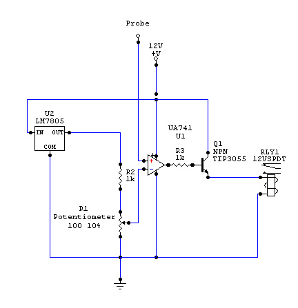
Date Posted: July 12, 2009 at 10:40 AM
I'm still working on the labels, and getting the hang of this program (Circuit Maker 2000) but this is basically the circuit?
Posted By: i am an idiot
Date Posted: July 12, 2009 at 1:53 PM
i am an idiot wrote:
I changed the value of the resistor that connects to the 7805. With the 1K resistor the control would be from 0 to (.)49 volts. With the 10K resistor you will have much better control.
Posted By: bigjohnny
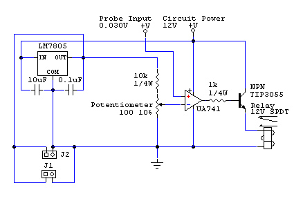
Date Posted: July 12, 2009 at 3:58 PM
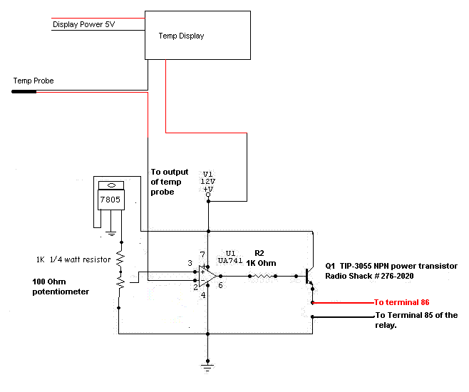
alright, so using my existing 7805 circuit, is this correct??
Also, adding this stuff to the existing 7805 circuit won't affect the connectors I have there to power the displays will it?
Posted By: bigjohnny
Date Posted: July 12, 2009 at 4:00 PM
forgot the freakin image
Posted By: i am an idiot
Date Posted: July 12, 2009 at 4:33 PM
All looks well. The extra load on the 7805 will be minimal. J1 and J2 are to power the displays?
Posted By: bigjohnny
Date Posted: July 12, 2009 at 5:00 PM
yeah, they are just connectors, I'm going to have to add two more to power the amp and volt meters, but Im waiting for my VB1212S-1W Isolators to arrive.
If only I had the stuff to make a PCB, that would rock.
I'll get the stuff to build this on wed or thurs and get it together.
Posted By: bigjohnny
Date Posted: July 17, 2009 at 7:23 AM
I picked up the parts but I have the transistor on order as well as the 100 ohm pot. a trim pot will work right?
I just have to find a perf board now, and get some connectors.
is there anywhere I can have a single PCB designed for this circuit? I don't want to have to buy a massive quantity of PCBs just so it can be made. I don't have thesupplies or knowledge to design PCBs.
Posted By: i am an idiot
Date Posted: July 17, 2009 at 2:27 PM
The circuit is really small enough to assemble on a project board. This one would be way more than enough area to do what you need. .radioshack.com/ 2102845------------- Let's Go Brandon Brown. Congratulations on your first Xfinity Series Win. LGBFJB
Posted By: bigjohnny
Date Posted: July 17, 2009 at 5:03 PM
I was actually looking at that. In the past I've used perf boards with single holes. I can see how that might be easier, but isn't it hard to place components on a board that has a "pattern" like that?
What would be the best way to connect the components, wires? again, with the single hole boards, I've usually just bent the leads to connect with each other. I haven't built anything big before, so that's always worked out ok, but I would like to know how others who assemble circuits go about the connections/pathways.
Posted By: i am an idiot
Date Posted: July 17, 2009 at 5:47 PM
The 2 strips in the center of the board are used as power and ground. Straddle the Chip over those strips. The chip will insert into the holes directly outside of the strips, this will leave you 2 available connections for each pin on the chip. If you have an old IDE ribbon cable for a computer hard drive laying around, a strand of that will make a great jumper wire. The ribbon cable will work great for your project. If you were doing something that requres more current, you will need larger wire.
-------------
Let's Go Brandon Brown. Congratulations on your first Xfinity Series Win. LGBFJB
Posted By: KPierson
Date Posted: July 17, 2009 at 7:13 PM
Check out www.freepcb.com and www.barebonespcb.com FreePCB is a free circuit board layout tool and barebonespcb is the best place I have found to buy custom "prototype" boards. Once you lay out a small circuit this way you'll never touch another perf board. On the perf boards, though, I used to actually solder the squares together (I would only use boards with square pads, the round pad boards always seemed to give me problems) to make traces. If I had to jump a trace I would use a small jumper wire. There are a million ways to do them, you just need to make sure they are laid out in a manner that allows easy trouble shooting. ------------- Kevin Pierson
Posted By: bigjohnny
Date Posted: July 17, 2009 at 10:28 PM
thanks for the advice guys, ribbon cable is perfect, and I'm gonna def. check out the program/site.
it's the layout for troubleshooting that gets me lol, I've only made simple circuits before, not that this is complicated but there are going to be more connections than I'm used to....sometimes gets a little confusing following a diagram.
I also got my isolators today, turns out they are 12v (I don't know why this just clicked in now tbh, I must be stupid or something) so I'm going to have to put them on the 12v side and step the voltage down AFTER the isolators, which means actually building another 12 v - 5v regulator circuit. I may just reclaim my existing one and use it for this.
The other isolator will be for my voltage meter, and will isolate the voltage being measured. that way it will all work to the specs of the meters.
It says they can't measure the same source either, which means I would need another isolator(vb1212s-2w, dual output) but the diagrams provided by the company show both meters measuring the same source when isolated with the dc-dc isolators.
I'll get some scans in a bit.
Posted By: bigjohnny
Date Posted: July 17, 2009 at 11:58 PM
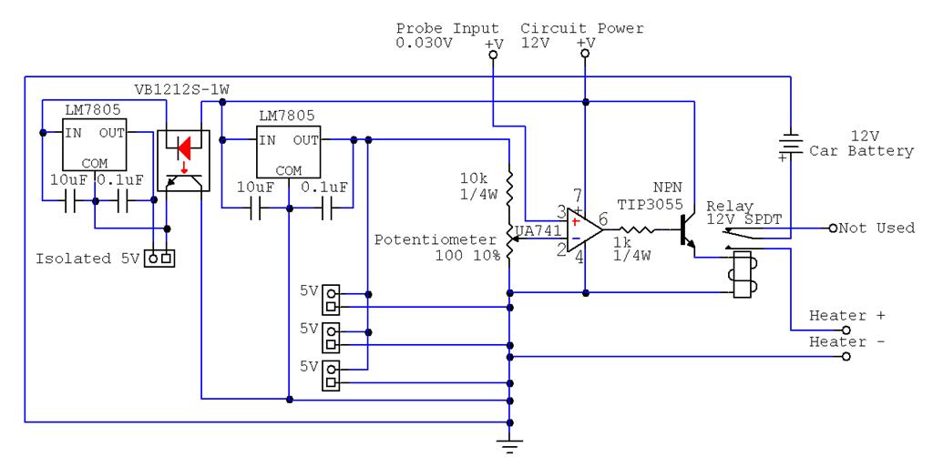
here is what the final circuit will look like I believe.
This provides me 3x 5 volt outputs to power the 2 temp displays, and the voltage meter, and an isolated 5v output to power the amperage meter, effectively isolating the voltage/current meters from each other.
The voltage meter will have an isolator on it's measure input, so both meters will also be measuring from an isolated source.
I don't know if the symbol for the isolators i'm using is correct, but for the purposes of this diagram it will work, the correct part number is shown.
I was looking at freepcb, I'm not quite sure how to use it, so it's gonna take a little time to learn, I'll probably just end up using the board that idiot mentioned above.
any suggestions for particular part placement on the mentioned perf board?
Here is how the two meters will basically be wired up
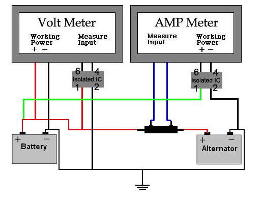
And the diagram of how the company says both meters should be wired with isolators, which totally contradicts what is said on the original diagram sent with these units.
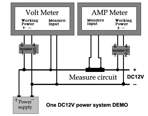
And this is the original diagram sent with the meters

Posted By: i am an idiot
Date Posted: July 19, 2009 at 9:51 PM
I would recommend connecting the heater negative wire directly to ground. It will take a huge trace on the circuit board if you connect it to the board.
-------------
Let's Go Brandon Brown. Congratulations on your first Xfinity Series Win. LGBFJB
Posted By: bigjohnny
Date Posted: July 20, 2009 at 7:26 AM
it wouldn't be connected to the board, I can't believe I did that, but it was more for a reference I thought I had shown it connected directly to ground.
but yeah, that wouldn't really be a smart thing to do.
Posted By: bigjohnny
Date Posted: July 21, 2009 at 7:38 AM
I'm unable to order one of the perf boards from radio shack because they don't have an option for shipping to Canada.
so where can I find a board to solder my stuff onto that will ship to Canada, the only stuff I can find locally is either huge, or simply the wrong layout.
Posted By: bigjohnny
Date Posted: July 24, 2009 at 6:59 PM
Well, I got this circuit built, haven't had a chance to fully test it as I haven't yet connected the temp probe, but the isolated circuit is producing 5v, the transistor has 12v output on pin 3, and except for putting the first isolator in backwards, appears to be working now. I just have to find some 2pin connectors of some sort, and put some finishing touches on the circuit before I can use it, and it might have to wait until next payday (3 weeks...ugh)
HOWEVER I now have to find another one of these damn isolators.
The info on the part is
"YAOHUA DY 12S12-1W" And I believe it's a DC-DC Isolated power supply or DC-DC Converter.
By mistake I had been looking up VB1212S-1W and it turns out this is a part also, and appears to be the exact same damn thing, I can't figure out what the differences are so I'm wondering if it's a number that's been cross referenced by pure coincidence.
Either way I need another one of these damn things, and I don't want to have to order one from the Asian seller I have been getting these meters/parts from.
How can I get some info on this damn thing because there is a good chance my local shop carries a similar part if I just knew what exactly this DY 12S12-1W was/is.
Posted By: KPierson
Date Posted: July 24, 2009 at 8:26 PM
Check out this: Murata NKE1212SC It's a 1 watt isolated 12vdc to 12vdc power supply available through digikey. ------------- Kevin Pierson
Posted By: bigjohnny
Date Posted: July 24, 2009 at 9:31 PM
I'll look into that... I also just realized I said damn 3 times in the previous post all of which referring to the isolators.... If I could edit that post I would edit those out, I didn't even realize I had done that.
From the price of those I might be better off getting them from the Asian guy, as he is selling me stuff at cost, and these are only $6.99USD through him, and at this point I've already spent about $100 or so between the meters, and various parts.
I've been having bad luck with burning things out...
EDIT AGAIN
He is going to send me another one, free. You know, I really cant say enough good things about this guy, he has great customer service, and some very interesting products. The seller is "giorgio11185", and his eBay store is "Asia Engineer"
I suggest if your looking for meters like the ones mentioned in this thread, to definitely check this guy out.
Posted By: bigjohnny
Date Posted: July 26, 2009 at 5:44 PM
I have a couple of questions about the potentiometer, I think I may have gotten the pins wrong.
The pot that I got is a 201UR101B, their is no pin data in the datasheet. Is pin 1 and 2 the ones that are side by side, and pin 3 is the one in the middle?
or are 1 and 3 the side by side ones.?
in the diagram, is the "ground"(the middle) the one which is connected to pin 2 of the op-amp?
transistor pin 2 gets 12v power?
op-amp pin 2 gets 12v power?
Posted By: i am an idiot
Date Posted: July 26, 2009 at 6:01 PM
The center pin on the diagram is known as the wiper. If it is a 1K potentiometer there are 2 pins that will always have 1K ohm across them, no matter the position of the wiper. Set the pot to the middle, using your meter find the 2 pins that read 1K. these 2 are the outside connections of the pot. Pot out of the circuit for testing.
-------------
Let's Go Brandon Brown. Congratulations on your first Xfinity Series Win. LGBFJB
Posted By: bigjohnny
Date Posted: July 27, 2009 at 7:03 PM
ok, I was looking for some assistance on getting a gerber file made up for the circuit so I could get a PCB made (or make one myself) and was asking around on an electronics forum, now they are telling me this circuit is basically all wrong.
I know it is a little inefficient since I don't do a lot of this stuff, and I've had to use extra parts to work with parts I already have (2x 7805's for each DC-DC converter so I have 5v, where if I BUY new ones I can get 12v/5v and reduce the number of parts) I'm sure I can reduce the amount of caps also. Perhaps just using the 1000uF cap I have to filter the entire circuit, instead of filtering each individual sub-curcuit.
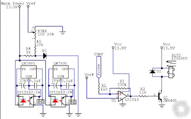
they say the 741 op-amp won't even work with such a low voltage, (1.97v less than the 741 needs to operate) and since I'm using it as a comparator.
The changes I made are reflected in the following diagram, their comments below.

Sch3mat1c wrote:
The 7812 won't do its job, it needs 15V or more. And you need protection stuff (forward diode, TVS and big 'lytic are a good combination) because automotive 12V is only 12V on average.
The 741 won't do whatever the heck you think it's going to do. Whatever "probe" is, 0.03V is 1.97V below anything the 741 can see. Use an LM358, which includes 0V. But since you appear to be using it as a comparator, that will still be awful. So use an LM393, which is a comparator, and a pull-up resistor on the output. But you show a 2N3055 emitter follower driving a relay, which is just silly. What's the relay really rated for? Maybe 100 ohms coil resistance? Use a 2N4403 and 2.2k resistor from LM393 output to its base.
As a plus, LM393 and 2N4403 both tolerate as much voltage as the 7812, so you don't need to worry about regulating their supply. You can still use a 7805 for voltage reference, but a zener diode or TL431 would be more typical for such a small source.
Posted By: bigjohnny
Date Posted: August 27, 2009 at 4:14 PM
ok, so the people at the other board seem to have stopped helping me, and i'm a little stumped here.
I attached the diagram I used with pin numbers and part numbers.
The first half of the circuit works fine, the vRef, it generates a varying voltage from 0 - 60mV when I turn the pot.
Nothing else works after that, the relay is getting nothing but 4.95v that doesn't change no matter where I turn the pot and the relay never gets activated.
So i dont know if i connected something to the wrong pin on this particular op amp but maybe someone here can help cause I really need to get it done my car has been apart long enough.
Posted By: bigjohnny
Date Posted: September 07, 2009 at 9:26 AM
anyone?
Posted By: liinstaller
Date Posted: September 09, 2009 at 8:20 PM
Looks like pin 1 should be the output.
Posted By: liinstaller
Date Posted: September 09, 2009 at 8:20 PM
If you're using an 8 pin DIP
|