To start, my car is an '01 Chevrolet Impala.
Well, I'm kinda a novice at car wiring, but I recently came into a ton of green LEDs, and green being my favorite color, I decided I would try to make my own LED strips to replace my current green neon kit in my car.
Got to thinking about it a bit, and for some reason, I'm confused. It's probably an easy answer, but for some reason I can't figure it out.
Here's the info on the LED
Reverse Current (uA) : <=30
Fv: 3.0v - 3.4v
Life Rating : 100,000 Hours
Max Power Dissipation : 80mw
Max Continuous Forward Current : 30mA
Max Peak Forward Current : 75mA
Reverse Voltage : 5~6V
I was reading alot about resistor this, resistor that. I came up with a few basic wiring diagrams.
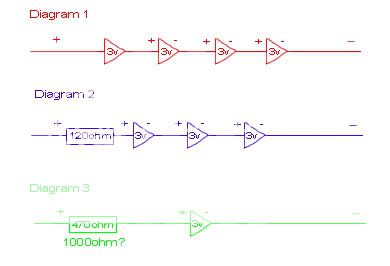
Now, I'm pretty sure all of these will work, not 100% sure on that. But the problem I was having was with paring these up... For some reason I can't figure it out. I want each strip to have 12 LEDs. Meaning that with Diagram 1, it'd take 3 "strips". Now do I need to wire each of the 3 strips to a common positive wire?
Like, how exactly could I get 12 LEDs on a strip in a series, without having 3 positive wires, and 3 negative wires? I'm sure I'm just being a moron. A diagram would be greatly appreciated. Thanks =D
Diagram 2 or 3 will work fine. Diagram 1 will fluctuate in brightness with alternator output. And the LEDs will not be as reliable.
I personally would go with #3 - that way if you have a problem with one LED no other LEDs will be affected. It will be a few more resistors, but in the long run it will most likely be worth it.
Your max forward current is 30mA and if you assume a max system voltage of 15 vdc your resistor value would be 500 ohms which would make it a 520 ohm resistor I believe. 470 ohms can result in an overcurrent situation and could shorten the life of the LEDs.
-------------
Kevin Pierson
Ok, so I'll go with the 500 Ohm resistor per LED setup. Does the wattage matter?
And to put my question up again.
How exactly can I wire these together into sets of 12?
I know it can't be
(+) --RESISTOR---LED---RESISTOR---LED---RESISTOR---LED---ETC-- (-)
Do I need to do something more like this
- RESISTOR - LED - (-)
|
(+) - RESISTOR - LED - (-)
|
- RESISTOR - LED - (-)
But to make a strip, that is going to take alot of wire.
So how would I go about putting these things onto a strip?
I would probably do it on a proto circuit board. Solder the resistor and LEDs in to the board and then connect all the powers and ground on the bottom of the board with solder.
-------------
Kevin Pierson
Cool, will do. Thanks =D
It might be a week or so before I actually get around to doing this.
But I'll try to post pictures when I do.