any 5v sources in the dash?
Printed From: the12volt.com
Forum Name: Lights, Neon, LEDs, HIDs
Forum Discription: Under Car Lighting, Strobe Lights, Fog Lights, Headlights, HIDs, DRL, Tail Lights, Brake Lights, Dashboard Lights, WigWag, etc.
URL: https://www.the12volt.com/installbay/forum_posts.asp?tid=112927
Printed Date: March 23, 2026 at 9:35 PM
Topic: any 5v sources in the dash?
Posted By: bigjohnny
Subject: any 5v sources in the dash?
Date Posted: April 05, 2009 at 7:06 PM
I'm getting a little temp gauge but its 5V not 12V, so Will it be easier to use a resistor to power it, or is there a 5v power source somewhere in the dash of a 1996 mercury cougar that I can tap into?
Replies:
Posted By: i am an idiot
Date Posted: April 05, 2009 at 9:45 PM
Do you know how much current the device needs?
Posted By: bigjohnny
Date Posted: April 06, 2009 at 6:56 AM
I'm not sure, it isn't listed, but I can't imagine it needing a lot of current.
Posted By: KPierson
Date Posted: April 06, 2009 at 8:09 AM
You can't use a resistor to drop voltage - resistors resist current. Go to Radioshack and buy a 7805. It is good for 1A, although that will be way more then you need. They are about $.99 from memory. There are three pins on the 7805 - in, gnd, and out. Connect the in to ignition voltage, connect the gnd to gnd, and the out is your output. Technically, you should put a capacitor on the input (10uf or so) and on the output (0.1uf or so). The caps will help stablize the voltage - they arn't 100% required but if your device is sensitive to voltage flucuations you should add them. For exact capacictor values consult the 7805 datasheet. ------------- Kevin Pierson
Posted By: bigjohnny
Date Posted: April 26, 2009 at 7:10 AM
would the displays ground and the regulator ground be connected together, or would it be better to connect the regulator ground and display ground separately?
Posted By: KPierson
Date Posted: April 26, 2009 at 7:22 AM
You can connect them together or apart, it doesn't matter, they just both need to be connected!
-------------
Kevin Pierson
Posted By: bigjohnny
Date Posted: May 02, 2009 at 12:26 PM
KPierson wrote:
You can't use a resistor to drop voltage - resistors resist current.
Go to Radioshack and buy a 7805. It is good for 1A, although that will be way more then you need. They are about $.99 from memory.
There are three pins on the 7805 - in, gnd, and out. Connect the in to ignition voltage, connect the gnd to gnd, and the out is your output. Technically, you should put a capacitor on the input (10uf or so) and on the output (0.1uf or so). The caps will help stablize the voltage - they arn't 100% required but if your device is sensitive to voltage flucuations you should add them. For exact capacictor values consult the 7805 datasheet.
what exactly am i looking for in the datasheet to determine cap values?
EDIT
nvm, I found this at the bottom of the sheet.
Note 2: All characteristics are measured with capacitor across the input of 0.22 μF, and a capacitor across the output of 0.1μF. All characteristics except noise voltage
and ripple rejection ratio are measured using pulse techniques (tw £ 10 ms, duty cycle £ 5%). Output voltage changes due to changes in internal temperature must
be taken into account separately.
Note 3: Absolute Maximum Ratings indicate
Posted By: bigjohnny
Date Posted: May 02, 2009 at 3:44 PM
so how do I wire the cap?
do I put power to one lead of the cap, and connect the other lead to the regulator input, or would it be one lead of the cap to power, and one to the regulator ground?
Posted By: KPierson
Date Posted: May 02, 2009 at 5:28 PM
Both caps need to be grounded and the other end of the cap needs to be connected to the correct power pin on the regulator.
-------------
Kevin Pierson
Posted By: bigjohnny
Date Posted: May 02, 2009 at 5:39 PM
So would it look something like this really doodiety diagram?
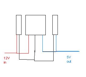
Posted By: KPierson
Date Posted: May 02, 2009 at 5:41 PM
yep
-------------
Kevin Pierson
Posted By: bigjohnny
Date Posted: May 07, 2009 at 9:05 PM
this thing works perfectly. I used a 12v transformer that actually put out 15V, and the output side of the regular circuit was a nice 4.95V
simple, and cheap.
I need to add some diodes somewhere though, Ive discovered that connecting power backwards to the displays burns out one of the tiny components on the board...... I found this out twice......
Could I use diodes in such a way that would allow it to work even if power gets connected backwards?
Posted By: KPierson
Date Posted: May 07, 2009 at 9:11 PM
I believe this will work: https://en.wikipedia.org/wiki/Diode_bridge ------------- Kevin Pierson
|