turn on/off neons with remote or switch?
Printed From: the12volt.com
Forum Name: Lights, Neon, LEDs, HIDs
Forum Discription: Under Car Lighting, Strobe Lights, Fog Lights, Headlights, HIDs, DRL, Tail Lights, Brake Lights, Dashboard Lights, WigWag, etc.
URL: https://www.the12volt.com/installbay/forum_posts.asp?tid=116369
Printed Date: May 06, 2026 at 1:32 PM
Topic: turn on/off neons with remote or switch?
Posted By: sigman70
Subject: turn on/off neons with remote or switch?
Date Posted: September 16, 2009 at 11:13 PM
Hello! I currently have the following setup in my 2002 Nissan Pathfinder - Streetglow underbody neon kit, hooked up via a switch with a relay (see picture below). Right now I'm able to turn the neon lights on and off by either the switch or my remote car start aux button. What I was wondering is could this setup be modified so that if I turned on the lights by the switch, I could then turn them off by the remote (and visa versa)? So if let's say I were to turn the neon lights on via the switch, then later I realized that I forgot to turn them off, I would like to be able to turn them off from the remote. Any help would be appreciated! :-) 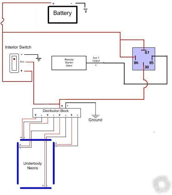
------------- sigman70
Replies:
Posted By: t&t tech
Date Posted: September 17, 2009 at 4:25 PM
You could do it via a relay, but you would have a constantly latched relay while the engine were off. Cheers.
-------------
Posted By: sigman70
Date Posted: September 18, 2009 at 1:20 PM
t&t tech wrote:
You could do it via a relay, but you would have a constantly latched relay while the engine were off. Cheers.
Thanks for the reply!! So what you are saying is basically my battery would end up being drained pretty quickly? I should have mentioned that I'm a total newbie at this...I had help from another forum in coming up with this current setup. I've been trying to get someone to show me with a diagram how I would go about changing this setup to do what I mentioned in my first post - but from what you are saying, it sounds like this wouldn't be a good idea? ------------- sigman70
Posted By: KPierson
Date Posted: September 18, 2009 at 1:38 PM
What about if you just hooked the cabin switch up to switched power? That way, you could never leave them on because the inside switch was left on, but you could still turn them on with your remote? You could also add a 2 input XOR gate (exclusive OR). You would wire the output of the switch to one input and the output of the relay to the second input. You would then need a transistor on the output of the XOR driving a relay. This output relay would then drive the lights. An XOR gate works like this:
Input 1 Input 2 Output
off off off
on off on
off on on
on on off
So, if you left one on input on simply toggling the other input would turn the lights off. ------------- Kevin Pierson
Posted By: t&t tech
Date Posted: September 18, 2009 at 6:45 PM
There you go, Kevin has a way of making thins work, doesn't he! -------------
Posted By: jaketime81
Date Posted: September 18, 2009 at 7:59 PM
there is a way to do what you want to do but you would have to change some things in your current set up. get a relay modual called ptr7. you can have your negetive output of your alarm trigger it to turn on and off your neon. if you took your switch and got one that throws a ground real quick you can have that switch activate the ptr7 to turn on and off. now seeing that both the switch and output of the alarm are on the same wire on the relay modual it will turn on when it sees ground and off the next time it sees a ground no matter were its comeing from. giveing you exactly what you want. also depending on your alarm you may want to put i diode on the output wire so the ground dosent back feed into the alram its self.
-------------
jake
Posted By: sigman70
Date Posted: September 20, 2009 at 10:04 AM
Kevin, thanks for the reply!! I'll be honest, I had no idea of what a 2 input XOR gate was, so I had to Google it. I think I may have found what I would need here: https://www.electronicthinking.com/inventory/12826-quad-2-input-xor-gates-74ls86. Can you tell me if this is the right part? Would you also be able to tell me what transistor I would need (this same site has some, but I'm not sure which one I need). If you have any suggestions on any places that might carry these parts locally (i.e. like a Radio Shack, etc.) that would be great, but if I have to get them via the internet that's fine. It sounds like I would need another relay as well, correct? After getting all the parts, I'll probably need to ask if I have everything hooked up right (I'll change my picture to reflect this setup) if you don't mind. Thanks again for the reply!! Jake, thank you as well for your response! I looked up the PTR7 - that looks like a pretty neat modual! I might go down this route if I can't figure out the XOR gate as this way is going to be cheaper. Thanks! -Dave ------------- sigman70
Posted By: KPierson
Date Posted: September 20, 2009 at 2:18 PM
Look in to this XOR: https://search.digikey.com/scripts/DkSearch/dksus.dll?Detail&name=296-2047-5-ND It can tolerate voltages up to 18vdc so it should work great in a car. For a transistor you can use a 2N3904. You'll also need a few other components (like a diode across the coil of the relay and a resistor between the output of the XOR and the base of the transistor (like a 470 ohm). ------------- Kevin Pierson
Posted By: sigman70
Date Posted: September 20, 2009 at 8:06 PM
Thanks Kevin for the link! I'm putting together my list of things to get - is there any particular diode I need for this? - Dave ------------- sigman70
Posted By: KPierson
Date Posted: September 20, 2009 at 8:53 PM
just a 1A rectifier diode will be fine.
-------------
Kevin Pierson
Posted By: sigman70
Date Posted: September 22, 2009 at 12:24 AM
Thanks again Kevin...after I get the parts I'll probably post again to ask about the connections (hopefully I haven't worn out my welcome!). I'll try to have a diagram as well. Thanks! -Dave ------------- sigman70
Posted By: sigman70
Date Posted: October 27, 2009 at 8:16 AM
Hello again Kevin...I finally got all (or at least I hope all) of the parts for this. I've tried to come up with a diagram of everything...I just am not sure how to hook all of this up! Do you think you could take a look and let me know how I would go about connecting everything? Thanks!! 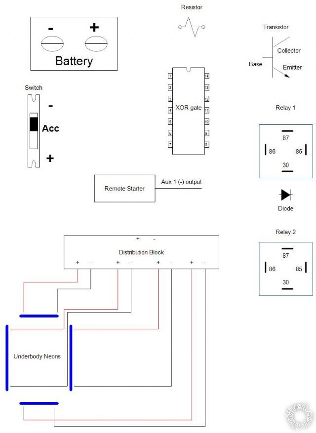
------------- sigman70
Posted By: KPierson
Date Posted: October 30, 2009 at 8:51 AM
 ------------- Kevin Pierson
Posted By: sigman70
Date Posted: October 30, 2009 at 9:17 AM
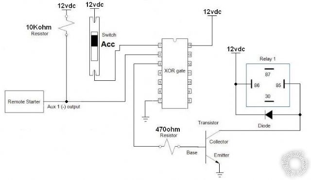
Kevin thanks for the reply on this! I wanted to check a few things on the diagram you filled out. - I should hook up the 12v source (battery) with a 10Kohm resistor to the negative output of the remote starter? This then gets attached to the XOR gate as shown? - For the switch...it looks like you have me hooking up the negative terminal of the switch straight to the XOR gate...so I don't need to use the accessory terminal on the switch? - I don't see where the neon lights are depicted...would I hook up the 14 pin on the XOR gate to the positive terminal on the distribution block for the neons? (on your diagram it shows the 14 pin going to the 12v source). - Would I need to have a circuit board to attach the wires to the XOR gate, or do you think I could just solder the wires directly to the XOR gate? Sorry for all the questions (which probably seem dumb)...just don't want to blow anything up when I try hooking this all up...lol. Thanks!! ------------- sigman70
Posted By: KPierson
Date Posted: October 30, 2009 at 9:41 AM
sigman70 wrote:
Kevin thanks for the reply on this! I wanted to check a few things on the diagram you filled out. - I should hook up the 12v source (battery) with a 10Kohm resistor to the negative output of the remote starter? This then gets attached to the XOR gate as shown?
Yes. The output of the remote start is "floating to ground". The 10Kohm resistor will provide voltage on the pin when the output is off, and will allow the ground to "seize the line" when the output is on. sigman70 wrote:
- For the switch...it looks like you have me hooking up the negative terminal of the switch straight to the XOR gate...so I don't need to use the accessory terminal on the switch?
I didn't really understand what you were showing on the switch, but now I do. I didn't realize you were showing a 3 pin switch. I don't have a ground connected to the switch - I only showed the input (+) and output (acc). Sorry for that confusion. Ground the (-) pin of the switch if it has one (ie if it is lighted). sigman70 wrote:
- I don't see where the neon lights are depicted...would I hook up the 14 pin on the XOR gate to the positive terminal on the distribution block for the neons? (on your diagram it shows the 14 pin going to the 12v source).
I didn't show them (obviously). I assumed you already had a relay running the lights and that when the relay is energized the lights turn on. This would be Relay 1. If you don't have a relay currently you will need to hook the neons up to Relay one (there are two different ways to do it, so I didn't bother showing any way). The "traditional" way would be to connect Pin 30 to 12vdc and connect pin 87 to the neon control box. Then, connect the ground on the neon control box to ground. sigman70 wrote:
- Would I need to have a circuit board to attach the wires to the XOR gate, or do you think I could just solder the wires directly to the XOR gate?
I would highly recomend a circuit board. The legs are flimsy and will fatigue and break if you solder wires directly to them. I would also recomend getting a socket and soldering it to the board, then putting the chip in the socket. You can get prototype boards at Radioshack (and similar places) that are designed for IC chips - that would be a good start. I would also try to find a board that is flexible enough to allow you to solder all the components needed to it (transistor, diode, resistors). sigman70 wrote:
Sorry for all the questions (which probably seem dumb)...just don't want to blow anything up when I try hooking this all up...lol. Thanks!!
No problems on the questions, sorry I wasn't very clear - I had a 10am meeting and wanted to get the picture done and posted before it started! ------------- Kevin Pierson
Posted By: sigman70
Date Posted: October 30, 2009 at 4:10 PM
Hey thanks Kevin for responding...I'm hoping I have this now! I've updated the diagram below - can you let me know if I have this right? I wasn't sure if I was supposed to leave pin 86 going to 12v source as well as pin 30? If this is correct (having both the 86 & 30 pins going to 12v source), then would the diode go just between pin 85 and 30, or would it go across all pins (85, 30 & 86)? 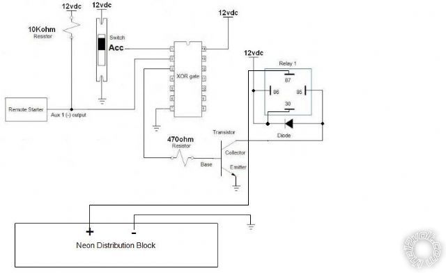
------------- sigman70
Posted By: KPierson
Date Posted: October 30, 2009 at 5:28 PM
Thats looks good as is. Don't forget to fuse as necesarry.
-------------
Kevin Pierson
Posted By: sigman70
Date Posted: October 30, 2009 at 7:48 PM
Hey thanks soooooo much for ALL of your help on this Kevin!! I really appreciate it! ------------- sigman70
|