two seprate circuits, one switch?
Printed From: the12volt.com
Forum Name: Lights, Neon, LEDs, HIDs
Forum Discription: Under Car Lighting, Strobe Lights, Fog Lights, Headlights, HIDs, DRL, Tail Lights, Brake Lights, Dashboard Lights, WigWag, etc.
URL: https://www.the12volt.com/installbay/forum_posts.asp?tid=118016
Printed Date: March 29, 2026 at 3:11 PM
Topic: two seprate circuits, one switch?
Posted By: two12
Subject: two seprate circuits, one switch?
Date Posted: November 25, 2009 at 6:58 PM
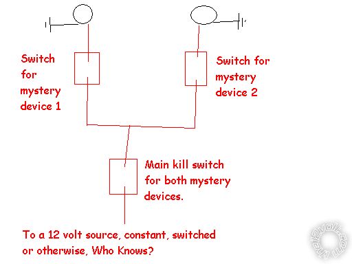
hello, is it possible to turn on two lights, each on a seperate circuit, together with one switch and still retain the ability to turn them on and off independantly?
example: have three switches total, first switch turns on/off light #1, second turns on/off light #2, and third turns on/off both light #1 and light #2
is this possible and if so how can I achive this?
thanks
Replies:
Posted By: i am an idiot
Date Posted: November 25, 2009 at 8:24 PM
Do you need to ever have both lights on at the same time? If not, I can do this with 2 switches.
Posted By: two12
Date Posted: November 27, 2009 at 10:29 PM
yes, Im using lights as an example.
I need two circuits to function both independently as mentioned and together with one switch.
any 12volt experts on here?
Posted By: stevdart
Date Posted: November 27, 2009 at 11:52 PM
No but I'll answer your question anyway. The answer is no. If you connect two circuits to one switch it will parallel the circuits Look through the vast array of switch configurations that are available for something that fits your needs. You are probably looking for one throw, but two switches. When asking for forum help it is better to describe your actual case rather than using an "example" that isn't actually what you are doing. ------------- Build the box so that it performs well in the worst case scenario and, in return, it will reward you at all times.
Posted By: i am an idiot
Date Posted: November 28, 2009 at 2:59 AM

And 2 of these, all available at RadioShack. 
But you will still need to find a 12 volt expert to wire it up.
Posted By: oldspark
Date Posted: November 28, 2009 at 8:12 AM
If they each have equal priority, I reckon it can be done with 3 push buttons.
Problem is, if #1 is on, & #2 is off, does #3 turn both on or both off?
If you want #3 to turn both on, that's easy enough with 3 on-off switches & 2 diodes, but for #3 to switch both off requires both #1 & #2 off.
If you define what you want (ie, a logic, truth or state table), an answer is possible.
Posted By: two12
Date Posted: November 28, 2009 at 8:14 PM
I say "using lights as an example" because the loads could be anything it doesnt matter and I dont want to confuse the question but I'll get into that later. I've many more unusual questions for the forum thats why Im looking for expert advice.
first things first.
a specialized switch wont work for me. the first two switches need to be in seperate onboard locations and the third via remote control.
switch #1 and #2 will generally be off when turning on #3
lets see what we can come up with here! this is just the warm up thread. Im not a 12volt novice by any means but I still have much to learn and Im really thinking out of the box on this project so just wait till you get a load of some of my next questions LOL
thanks
Posted By: i am an idiot
Date Posted: November 28, 2009 at 8:16 PM
Topic: two seprate circuits, one switch? I am confused.
Posted By: two12
Date Posted: November 28, 2009 at 8:41 PM
i am an idiot wrote:
Topic: two seprate circuits, one switch? I am confused.
no youre "an idiot" couldnt resist..
I tried to squeeze in a good title but the forum doesnt allow enough spaces for one so it is what it is.
so what would i am an idiot name this topic? I'll change it if I can and it gets results.
Posted By: KPierson
Date Posted: November 28, 2009 at 8:57 PM
You use lights as an example, but how much current draw are you trying to design this to control?
-------------
Kevin Pierson
Posted By: i am an idiot
Date Posted: November 28, 2009 at 11:06 PM
Posted By: oldspark
Date Posted: November 28, 2009 at 11:40 PM
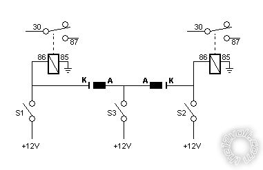
If we call switches #1, #2 & #3 S1, S2, S3....
Then how about:
S3 turns both on (overriding S1 & S2) and...
If S3 is off, S1 & S2 determine the state (ie, S1 on & S2 off means each load is on & off respectively.
That is easy with plain toggle switches, 2 diodes, & 2 relays.
If that is not the operation you want, then explain the change(s) you want.
Posted By: two12
Date Posted: November 29, 2009 at 12:26 AM
guys, theres no mystery here, the loads are lights. current draw is irrelivant at this point. I just want to learn how to control two seprate circuits in this manner. I havnt even got to the confusing stuff yet lets not jump the gun LOL
IAAI, thanks for taking the time to draw me a picture! I wish it was that easy.
oldspark, heck yeah! I think that is what Im after, Im ready! with a common 12vdc source (for now) and *lights* ;-)
Posted By: oldspark
Date Posted: November 29, 2009 at 1:28 AM
Lights? What do you think I am - confused?
This is toooo EEEEASY!
Ooops - re-edited with correct switch labels.
And note that S3 will power S1's & S2's upstream sources, but 2 more diodes will prevent that too.
Posted By: KPierson
Date Posted: November 29, 2009 at 7:33 AM
Great drawing oldspark! Now that we know "current is irrelevent" I redrew it a little and added some part numbers. This drawing, with these parts, will truely be automotive save at virtually any current level. If, for some reason, your battery is capable of more then 1200 instantanious amps you may want to add a 5th AEV19012W and go with slightly larger diodes and switches. All these parts are available at www.digikey.com! 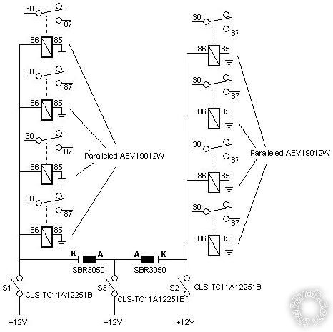
------------- Kevin Pierson
Posted By: oldspark
Date Posted: November 29, 2009 at 8:18 AM
LOL!
But it's unfair twisting 2-12's " current draw is irrelevant at this point" to being a high current draw.
Novices may try to implement 4 relays to boost current rating and then wonder why contacts fuse or relays smoke!
If needing that for say 1000A, I'd be looking at an SCR!
(Or at least have SCR-quenching across each contact!!)
Hey 2-12 - we have a "Red Rooster" ad down under here that has a soon-to-be classic line "Some people just don't get it!".
It has interesting relevance (Hint: It wasn't set in Australia)  
Posted By: two12
Date Posted: December 02, 2009 at 6:44 PM
oldspark, thats it right there! very simplistic.. even I can manage that.
now, would it matter if S1 & S3 source was seperate 12vdc than S2 but still common ground? (two seperate and isolated batteries) if so what would change?
and whats SCR?
KP, thats nice to know but Im not understanding how paralleling relays increases current capibility..
is that why the "just dont get it" comment OS? is KP's diagram failure prone or is it just me ;-)
Im not trying to operate two seperate winches or anything that loaded.
Posted By: i am an idiot
Date Posted: December 02, 2009 at 7:02 PM
SCR = Silicon Controlled Rectifier
Posted By: KPierson
Date Posted: December 02, 2009 at 8:48 PM
The point of my drawing was to show that current is in fact relevent. Designing a circuit to handle 100mA of current will be different then a circuit to handle 1A or 10A of current. Paralleling contacts will increase the theoretical load (as the side of the contact is what determines how much current can pass). You will, as oldspark mentioned, increase the risk of welding contacts. However, that isn't why my drawing was impractical - it was impractical because it would cost around $5,000 to build. It would safely handle 600A of continous current and up to 1200A peak. If you want us to help you design stuff you should provide specific guidelines to follow, otherwise we'll just hav fun with it. ------------- Kevin Pierson
Posted By: oldspark
Date Posted: December 02, 2009 at 10:32 PM
Hi Two,
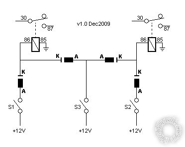
It won't matter if the voltages are from different sources provided you add the extra diodes as shown in the updated dwg below (Version-1).
As mentioned before, they each switch powering the other switches.
(Current can only flow out of the K = Cathode end, not into it.)
Hence different battery/source voltage levels won't have any effect.
(That's assuming a common earth/ground as you stated, and that each source has enough voltage to energise the relay(s).)
If mixing different voltages - say 5V, 12V, 24V etc - then you would use ground switching on hot relays. But that's probably not required here. ("Open-Collector" outputs refer.)
FYI - I've done a similar design where a vehicle has its standard electrics, but a second alternator and two batteries have been added. Except for common chassis/ground, they are independent (although the orig alternator can charge the 2nd & 3rd batteries if the 2nd alternator isn't charging.)
And forget about SCRs, triacs etc. (Unless you are switching several thousand Amps DC lol!, or maybe AC.)
As to the importance of the current being switched, maybe it's because I break solution down into respective parts, but I agree with...
two12 (paraphrased) wrote:
..there's no mystery here.... current draw is irrelevant at this point...
(I can hear T'ilk saying "Indeed!".)
In this case, the load does not impact the "front end" design.
(The FE is whatever it has to be - in this case a logic circuit.)
If the load is too big for the circuit (switches), you power the load via relays.
It's the same with anything. If the load is bigger than what a CPU etc can handle, you buffer it with whatever it takes - FETS & transistors to relays to contactors etc.
The load current might effect the final implementation.
If they were LEDs, we'd probably just use a hex inverter chip, 3 push buttons & a few Rs & Cs.
If they were AC or DC lamps, then maybe be used Triacs or SCRs, or contactors for sodium lamps etc.
Is there something that I am missing?
How would (say) my design change if the output were a few giga-Amps other than that the switches would power relays powering other relays etc until the desired amplification/fanout is achieved)?
Posted By: two12
Date Posted: December 13, 2009 at 4:26 PM
just wanted to say thanks again guys.
I think oldspark's design will be perfect for what I have in mind but now I have to find time to impliment it.I'll report back with my results or further questions depending on what I get into here.
Posted By: two12
Date Posted: December 16, 2009 at 7:15 PM
OK

this works exactly as expected. thanks again OS!
now how would this diagram change if S2 controlled LED fog lights?
I assume I can eliminate the relay shown on the top right but everything else in this diagram remains the same for this purpose, no?
thanks
Posted By: oldspark
Date Posted: December 16, 2009 at 8:02 PM
two12] wrote:
his works exactly as expected...
OF COURSE! What did you expect?
(READ: Phew - I fluked it yet again! No misunderstandings, no stupid errors.)
And you are correct about NOT having relays.
The relays are mainly there to take the load of the switches and diodes.
They also allow full voltage to the load (ie, no diode voltage drops) or allow total independence of the load (eg, a 24V or 48V loads etc; maybe AC loads with appropriate relays and regulatory conformance...)
If the LED foglights are within switch and supply tolerances, and diode rating (1A, 3A, whatever), then no problem. They will be a bit dimmer though (eg ~0.7V in ~12V "dimmer").
Remember the diode's heat - ie, ~0.7 x I Watts where I = current (Amps).
|