led circuit
Printed From: the12volt.com
Forum Name: Lights, Neon, LEDs, HIDs
Forum Discription: Under Car Lighting, Strobe Lights, Fog Lights, Headlights, HIDs, DRL, Tail Lights, Brake Lights, Dashboard Lights, WigWag, etc.
URL: https://www.the12volt.com/installbay/forum_posts.asp?tid=118206
Printed Date: April 07, 2026 at 10:48 PM
Topic: led circuit
Posted By: no_joke_chevy
Subject: led circuit
Date Posted: December 03, 2009 at 12:09 PM
hey guys ive a problem im trying to build these circuits and everyone i try is based of 6 or 9 volts how would i change it to be based on 12v heres one for example thanks for ur help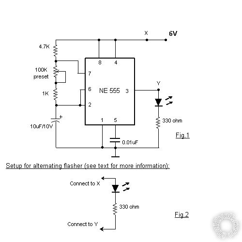 or or 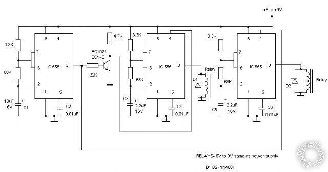
Replies:
Posted By: ckeeler
Date Posted: December 04, 2009 at 10:39 AM
i dont understand your question. have you even tried building this circuit with a 12v feed? NE555 timers are good up to 40v if im not mistaken. build it and try it. you may have to tweak the resistor and capacitor values to get the timing you want, but hey, thats easy enough. replace the suggested 6v relays in the schematic with ones that have 12v coils and you'll be golden. just give it a shot and tweak it from there it will work.
Posted By: ckeeler
Date Posted: December 04, 2009 at 11:02 AM
also, i noticed the caps in the schematic are 16v ratings. use 25v caps instead.
Posted By: no_joke_chevy
Date Posted: December 04, 2009 at 11:58 AM
THANKS FOR YOUR HELP I HAVEN'T HAD TO MUCH LUCK ON THIS SITE WITH HELP SO EVERYTIME I GET HELP I REALLY APPRECIATE IT....sorry for the caps just noticed and im doing this on my new phone and it tooke me for ever
Posted By: ckeeler
Date Posted: December 04, 2009 at 12:14 PM
no problem. there is usually tons of of help on this site. maybe it's been slow lately? at any rate you should be able to use a 12v feed on that circuit without ant problems at all.
Posted By: KPierson
Date Posted: December 04, 2009 at 4:08 PM
Double check your 555 outputs and make sure they are capable of directly driving a relay - I wouldn't be surprised if you need a transitor to drive each relay, but I haven't messed with a 555 for years. Where is oldspark? :)
-------------
Kevin Pierson
Posted By: ckeeler
Date Posted: December 04, 2009 at 4:24 PM
a 555 does not need a transistor to drive a relay coil.
Posted By: oldspark
Date Posted: December 04, 2009 at 6:40 PM
Fear not avid readers! The OldSpark has rekindled the old 555 circuit's (brain) cells....
(Thank you KP - I am honoured!)
Increasing the voltage to 12V:
I agree - increase cap rating to 25V (or higher). (It's recommended to have a good voltage rating margin.)
And relays to 12V.
The LED's 330R resistor can probably stay as is PROVIDED it is rated for 1/2W - it'll just be brighter - but 820 Ohms would be its equivalent 12V value, else anything in between. (820R 1/4W is fine, but stick to 1/2W - traditionally they were considered robust etc.)
Similarly the BC107/148's 22k to 33k - but that's probably insignificant since it's merely acting as a signal inverter (no load) and well withing its capabilities.
The timing will not change - it's an RC time constant where all voltages are proportional to the supply voltage (ie, RC voltage and the 555's comparator voltages - FYI: which are 1/3 & 2/3 of the supply voltage).
The 555 can source and sink 200mA.
At 12V, V=IR hence R=V/I = 12/.2 = 60 Ohms.
Hence it should drive relays with solenoid resistance HIGHER than 60R (I use R as shorthand for Ohm instead of the Omega symbol).
BUT!!! - if by 12V you mean "vehicle", that could be 14.4V, though I will usually design for 16V.
The same V/I = 16/.2 = 80R.
Why did I do that? Because many automotive 12V relays are ~68 Ohm and hence a borderline case. (There are reasons why they usually are ok, but is it worth risking?)
But I like transistors for the heavier outputs - they buffer the 555, are cheaper to replace etc, though is is another point of failure....
IMPORTANT!! None of your circuits show "decoupling capacitors". These are merely 0.1uF caps across the power supply to snub transients - especially in the triple 555 circuit (TT5 = triple triple-5 circuit?).
Place a 0.1uF cap across each 555's pins 1 & 8 and as close as possible to them.
The 555 can generate a big switching transient which can unintentionally trigger other circuits an 555s.
Often a larger cap may be used across the supply as well (1uF or 10uF electrolytic cap with 25V rating) bu that would accompany other protecting in automotive circuits (zenor/voltage protection, series resistor etc) but wouldn't be required from a clean power source with adequate cabling.
How'z that for a dusty old brain?
My last 555 build was.... not in this millennium.
Though a few years ago I got the components for a wiper delay and a headlamp dimmer for my ute (pick-up), and a camping 12V fluoro-lamp dimmer.... Can't rush these things you know.
Besides, for some reason I keep getting distracted...
BTW - It's bad if you don't get replies - unless you have posted bad eksprzion, though I will often skip non-informative topic headings/subjects.
Otherwise a bump may be worthwhile (certainly after a few days).
The best thing though is getting the good replies - like CK & KP above. (If CK hadn't have detailed all that, I would have missed most details. It may have been a shorter answer, but maybe your 330R would have smoked, and your tt5 circuit false triggered.)
|