single led blinker/parking without relays
Printed From: the12volt.com
Forum Name: Lights, Neon, LEDs, HIDs
Forum Discription: Under Car Lighting, Strobe Lights, Fog Lights, Headlights, HIDs, DRL, Tail Lights, Brake Lights, Dashboard Lights, WigWag, etc.
URL: https://www.the12volt.com/installbay/forum_posts.asp?tid=119752
Printed Date: March 28, 2026 at 12:43 AM
Topic: single led blinker/parking without relays
Posted By: assassin10000
Subject: single led blinker/parking without relays
Date Posted: January 30, 2010 at 1:15 AM
Hi, I want to use the single LED in my marker/corner light(s) as both turn signal & blinker. Here's what I'm looking for it to do: 1. Blinker on, Parking off = Blinks. 2. Blinker off, Parking on = On solid. 3. Blinker on, Parking on = Blinks. Now, here's the difficult part, I don't want to use relays! Instead what I want to do is use a few small JFET transistors (NTE457), diodes, & resistors. for a more compact setup. From what I understand JFET transistors are normally 'on' and turn off once voltage is applied to the 'base'. Here's what I've come up with, but I'm not yet sure on the resistor needed. 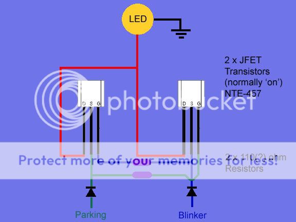
OR, if possible using an Integrated Circuit, NTE858M which has dual JFET's... Really not sure about this one though. I do NOT mind that the blink is 'offset' when the parking light is on. Thanks, Andrew
Replies:
Posted By: oldspark
Date Posted: January 30, 2010 at 11:12 AM
Alas the logic is flawed.
The LED will be on whenever the parkers are on. (If not powered from the blinker when on, then from park when the blinker is off.)
With these "blinker-overrides (other things)" circuitry, there needs to be a delay function. (Unless you access the selector switch - but that involves more complex switching, but delay circuits.)
Or have I analysed the circuit wrong? (I hate "physical" diagrams!)
Posted By: assassin10000
Date Posted: January 30, 2010 at 4:34 PM
I think you may have read it wrong. Looking at the diagram think of this:
D = 87a
S = 30
G = 85&86
On a relay.
Does that make it easier for you to comprehend?
Link to the jfet transistor:
NTE 457
Posted By: oldspark
Date Posted: January 30, 2010 at 7:36 PM
Ha! Thanks - but I've only recently started using relay "labels" for the sake of others.
But as I have drawn it, it's almost a flip-flop circuit...
VIZ:
2 "parallel" JFETs with joined D
Each G connected to the other's S (via resistors)
LED to ground from D
With one S from Park, the other from Blinker (both via diodes).
Yep - that checks with with your diagram. (??)
So...
Blinker off & Park is on hence supplying LED thru its S-D, and turning off Blinker FET. (LED is ON)
Blinker on & Park on - aha - both are off... was that my error?
Checking the rest....
Both off means both JFETs open, but no power so LED off.
Blink on & Park off is as first above, but LED powered thru Blinker's S-D.
So if Parkers are on, the LED blinking is inverted (big deal!).
And if you sit there and turn the Parkers on & off in phase with the blinker, then the LED is continuously off, else on...
See - I told you it was flawed. (LOL!!)
Now I'm sitting here thinking htf have I missed this circuit before?! (My misdiagnosis above doesn't bug me....)
And I recall your original statement to which I was going to respond "no - they are off until turned on".... But JFETs..... Dammit! I was taught JFETs in school! But the only FET circits I've designed have been recently using MOSFETs etc. And yes - JFETs are "on until turned off" - aka an NC relay (30-87a) as you said!
Yet another smartA Rookie that doesn't need help!
THANKS!
So the issue then is the resistor which need to be large enough so as to NOT burn out the FET due to G-D current, but small enough to pull down to somewhere under 6V G-S (2V? 1V?) - I'll need to check....
And that the FET is handling (say) 20mA....
Yes?
(I'll leave it for a while. I've been saying I need to cool off - today is high-30s (C - ~100F?). Besides, I need to rejoice over a "common reverse & indicator bulb issue" that (er, um...) I have just solved. No RC delays, no DPDT relays. And it is a straight plug-in (interception) - not a "rewire". FIGJAM!
Or rather FYGJAM!!)
 but really 
Posted By: assassin10000
Date Posted: January 30, 2010 at 10:36 PM
Sounds like you've got the idea behind my diagram now
I think the last thing to get figured out is what resistor to use to cross the opposing S/G terminals/triggers. The max off voltage is 6v, min is about .6v; so at this point I'm thinking dropping it in the 2-3v range with an input that varies from 11.5-14.5v is ideal.
IIRC, to get around 6v for an LED you'd use a 470 ohm resistor at .02 amp. And according to the site I bought them from (5 years ago) the wide angle LED (168/194 wedge style base) is rated around .015 amp (Others list the same style at .018 amp).
12.5v - 2.5v = 10v drop needed
10/.015 = 667 ohm
So, 680 ohm is the closest standard size resistor. That should do it right? Or do I need to treat the resistor as if its on a parallel circuit and calculate off the JFET? I'm not sure what the value would be then.
Andrew
Posted By: oldspark
Date Posted: January 31, 2010 at 12:19 AM
680 is about right for a 20mA off a 12V system.
It could well be lower because of Rds (less Igd??).
Alas I broke out my old Sedra & Smith and started to read...
But I still want to have a swim. At least I should have more time - I don't think I'll be seeing the girlf for a while. (Some people just ain't as enthused as I am! Others get their priorities wrong.)
I merely considered that if the FET's current is a problem - ie, I want to drive 2A bulbs - it's so simple to add a $2 MOSFET...
But, back to the LED resistors. I don't think we can have both JFETs on - that avoids parallel DS resistances.
So it's just Rds in series with a series LED resistance, but add in any G current too.
But if the JFETs could be configured for constant current - ie, 20mA.....
I'll get back to you....
But honestly, it can't be this simple...????
Posted By: assassin10000
Date Posted: January 31, 2010 at 4:39 AM
oldspark wrote:
But, back to the LED resistors. I don't think we can have both JFETs on - that avoids parallel DS resistances. So it's just Rds in series with a series LED resistance, but add in any G current too. But if the JFETs could be configured for constant current - ie, 20mA.....
I'll get back to you....
But honestly, it can't be this simple...????
Well, that's why it's configured so that if one see's voltage, it shuts the other off. The response time should be high enough that there won't be any issues there either (or so I'm guessing). When both JFET's happen to be on... both the blinker & parking are off. So it's a non-issue (again, so I 'think'). I'm unsure what the actual current for 'G' is, but according to NTE (the MFG) it's max rating is .010 amps, and it will probably be a lot less (guessing). It may be a simple circuit, but I have spent 2-3 days doing research on available semi-conductors to 'find' the JFET's and get a basic understanding of how they work... and even then I didn't come up with the above idea immediately. I spent a solid day trying to figure something out and came up with nothing but either a 3 relay setup (for both L&R) or 4 relays (2ea side). This came to me the following day after I gave up for the night. Andrew
Posted By: assassin10000
Date Posted: January 31, 2010 at 5:39 AM
Again, just spent some time looking over NTE's info/site. https://nteinc.com/Web_pgs/FET.html & https://www.nteinc.com/specs/400to499/pdf/nte457.pdf Near as I can tell, the current/amps necessary to bring DS voltage to zero varies from .001-.005 amps. To quote NTE, "Drain Current Zero - Gate Min-Max (mA) : 1-5. And average is 3 mA." Leaving me to think total amps necessary is going to range from .016 A (min) - .023 A (max). Just had another thought, do I need to take into account the resistor/resistance that's built into the wedge style LED? I just verified they are constructed with both a resistor and additional diode for safety. Measured 447 ohms with a multi-meter, which is right at the 5% tolerance limit of the standard 470 ohm resistors used when wiring in single LED's. Or maybe not, since the Transistor that is ON is setup with the resistor & GD in parallel with the one being shut OFF. That would mean it's not a problem, correct? As both the LED & the GD seeing voltage will be receiving 12v due to the parallel circuit there. Wouldn't that mean the current would be split on the two legs then recombine where the two D's combine and voltage would remain as 12v for both (If I'm thinking about this right). Andrew
Posted By: yakuzahi
Date Posted: October 30, 2010 at 8:56 PM
The "D" "G" "S" stand for the: NTE 457
and not for 5 Leg relay!
-------------
Z@)-)i
Posted By: yakuzahi
Date Posted: October 30, 2010 at 8:58 PM
assassin10000 wrote:
I think you may have read it wrong. Looking at the diagram think of this:
D = 87a
S = 30
G = 85&86
On a relay.
Does that make it easier for you to comprehend?
Link to the jfet transistor:
NTE 457
The "D" "G" "S" stand for the: NTE 457
and not for 5 Leg relay! ------------- Z@)-)i
Posted By: oldspark
Date Posted: October 31, 2010 at 3:13 AM
Why would it be for a 5 leg relay?
If you have a point or a question, please rephrase.
If you are a spammer, please include a link.
Posted By: assassin10000
Date Posted: October 31, 2010 at 4:53 AM
^ ditto.
Unfortunately my efforts to build this didn't end up working. Even though it was sound in theory, the LED devices I was trying to power probably took more juice than could be provided by the transistors.
Andrew
Posted By: oldspark
Date Posted: October 31, 2010 at 8:27 AM
FYI - I did state 'I wonder why I didn't think of this for my flasher/reverse lights'.
Later I realised the catch - the flasher-can has to see the full load, hence too the JFET(s).
I probably did think of using JFETs, but then discarded the idea.
I still reckon there must be a way - using a DPDT relay (per side) feels like overkill, and I'd rather intercept normal indicator wiring (ie, can before the left-right switch) as well as only switching for the rarer reverse occurrence...
Maybe next month. (I finally fitted my (head)light reminder buzzer today. That's taken 10 years - for my current vehicle....)
Thanks for the update.
I'll re-awaken this thread else PM when I get any brilliant thoughts...
Posted By: i am an idiot
Date Posted: October 31, 2010 at 8:50 AM
G S and D are the designation for the legs of a Mosfet transistor. G in the gate, S is the source, and D is the drain. Basically the Gate is what controls the transistor. Turn the Gate on and current flows from the source to the drain.
Posted By: oldspark
Date Posted: October 31, 2010 at 8:58 AM
Assassin and I know that - we are talking about J-FETs.
For some reason yakuzahi reiterated what we know... I suspect innocently (not spammingly etc).
The benefit is Assassin's update, and that I always wanted to explain why I missed the "obvious" use of a JFET for my application.
So now we are up to date.
And still seeking an elegant solution.
Posted By: assassin10000
Date Posted: October 31, 2010 at 4:47 PM
I looked at dpdt relays too, but couldn't see a way for it to work the way I wanted it to. Possibly with a capacitor, but for the time being I'm leaving it alone. Currently my cornering lights that are supposed to come on solid with turn signals are wired in to come on with my parking lights.
I am well aware with 2 relays and signal taken before the flasher I could make it work. Just don't feel like running the extra wires/relays at the moment. I've got enough wiring going on (standalone ecu & modern engine with dual variable valve timing) for my motor swap to worry about. I may revisit doing this at a later date.
Andrew
|