new dome lights with new switch wiring
Printed From: the12volt.com
Forum Name: Lights, Neon, LEDs, HIDs
Forum Discription: Under Car Lighting, Strobe Lights, Fog Lights, Headlights, HIDs, DRL, Tail Lights, Brake Lights, Dashboard Lights, WigWag, etc.
URL: https://www.the12volt.com/installbay/forum_posts.asp?tid=120131
Printed Date: March 19, 2026 at 5:47 PM
Topic: new dome lights with new switch wiring
Posted By: ajan246
Subject: new dome lights with new switch wiring
Date Posted: February 14, 2010 at 9:52 PM
Ok guys here is what i got. I have a 97 nissan pickup. What i did was replace the single dome light with 4 cold cathodes. There are 3 wires going to the old dome light. RED / black, RED / green, and black. These wires are for the door pin switches that control the on/off/door function of the dome light. What I am trying to do is have the new dome lights come on when either of my door is open; be able to turn the lights off while either door is open, and be able to turn the lights on while the doors are closed. I did some testing and these are my results:
RED / green - 12v constant
RED / black - not sure (i know its negative though)
black - negative/ground
i have 12v between: RED / green and black
RED / green and RED / black
but i can't figure out the wiring for my switch. I don't even know if what i want is possible with what i have. I'm just using a 3 prong switch its an automotive switch with an LED.
One of these.

any help is appreciated! Thanks!
-ajan246
Replies:
Posted By: oldspark
Date Posted: February 14, 2010 at 10:39 PM
Without looking wiring figs nor knowing your model etc, the RED / black is probably the door switch. I presume your exiting dome switch selects off, door, or on - the same as you want.
If so, no wiring changes are required.
If you want a remote "master on" switch, parallel the door or "on" switching.
For master off, you need to break the connection - probably power.
Most door switches are single-wire grounding, but can be 2-wire and either grounded or hot (+12V).
See also led triggered by dome light and on/off/on (page 2) that has the image below.

Posted By: ajan246
Date Posted: February 15, 2010 at 12:22 AM
can anyone explain this diagram? I'm not sure what i'm looking at.
Posted By: oldspark
Date Posted: February 15, 2010 at 3:42 AM
The left side might be the same as your vehicle's wiring.
The RHS is the added LED or LEDs with resistor, and a 3-position switch for on, off and whatever the dome selector switch is (that's with the RHS switch as it wipes from right (3) to left (1)).
If instead you want on, off & door, then connect the leftmost (1) of the RHS switch to the door switch(es) - ie, middle terminal of the dome selector switch (assuming it has 3 positions - namely off, door & on).
Posted By: 97accord
Date Posted: April 18, 2010 at 3:29 AM
can anyone explain what the lighting rods is?
also where is that 12v zig zag attached to?
also did anyone oldspark way to wire the switch to the led's and dome?
Posted By: i am an idiot
Date Posted: April 18, 2010 at 6:53 AM
The lightning rods indicate that the things next to it are LEDs. Light Emitting Diode. The lightning bolts are the light coming from the devices. The Zig Zag you are refering to is a resistor. The resistor should be connected to a constant 12volt feed.
Posted By: 97accord
Date Posted: April 21, 2010 at 12:50 AM
has anybody used this method to turn their interior light like this...if you did does it work like this
Dome off +switch off = no light
Dome off + switch on = light
Dome on + switch OFF = light
Posted By: 97accord
Date Posted: April 21, 2010 at 1:56 AM
also is oldspark setup can only be use with a 3 way switch....or can i use a 2 way switch
Posted By: 97accord
Date Posted: April 21, 2010 at 1:59 AM
does anyone know how high of a resistor i need to get
Posted By: oldspark
Date Posted: April 21, 2010 at 3:07 AM
97accord wrote:
has anybody used this method to turn their interior light like this...if you did does it work like this
If using my diagram, it'll be:
Dome off + switch off = no dome nor LED
Dome off + switch on = LED
Dome on + switch OFF = dome
Dome on + switch on = dome & LED.
Dome = door etc - as above where ON = door open (switch closed to ground).
This should be explained in the link - IE - assume the left side is the normal Dome wiring.
The extra RHS 3-position switch is for LEDs to (1) light with dome; (2) be off; (3) be on.
Use a 2-way switch if one of the above positions is not necessary.
If the LEDs are ~3-3.4V, you might not need a resistor.
Assuming you have the 4 LEDs in series, and Vf is the LED voltage drop at current I (eg, 1.7V or 3.4V @ 20mA = 0.02A), and VS is the supply voltage, then the resistor size required is (from V=IR =>R=V/I):
R (Ohms) = (VS - 4xVf)/I
EG assume worst case: R = (15 - 4x3.4)/0.02
= (15 - 13.6)/0.02
= 1.4 / 0.02
= 70 Ohm.
Hence use nearest preferred value of 68 Ohms or 82 Ohms.
The resistor's power rating should be I x I x R
EG = .02 x .02 x 82 = 0.03W, hence a 1/2W (recommended size) is ample. Although 1/8W = 0.125W is also ample, they are physically small etc.
Posted By: 97accord
Date Posted: April 21, 2010 at 4:12 AM
i just wanted to turn the floorlight on and off not with led and dome both on so the 2 way would be right for me right?
also with your your setting will the switch turn on only the led even if the dome light setting is set to the door open setting
and when the led switch is set to off.... will both the led and dome light turn on when the door opens?
so the + from the led connects to the + of the dome wire...or can i just add a wire to the dome + terminal will that work also?
and the - from the led connect to the car metal?
Posted By: 97accord
Date Posted: April 26, 2010 at 4:10 AM
can anyone help me with oldspark method of wiring led light's
Posted By: oldspark
Date Posted: April 26, 2010 at 4:33 AM
If nobody else offers, what do you have difficulty with?
And you draw your existing system?
Posted By: 97accord
Date Posted: April 27, 2010 at 2:03 AM
hey oldspark i had post a message on april 21 i was wondering can you help answer my question cause i can't repeat my question.....thanks
Posted By: oldspark
Date Posted: April 27, 2010 at 2:14 AM
But I answered that (all of them).
Yes!
Posted By: 97accord
Date Posted: April 27, 2010 at 3:56 AM
k so wait so even those i use a 2 way switch and it is set to off and my interior light i set to door setting so my dome and led light both turn on when the door opens is that right?
Posted By: 97accord
Date Posted: April 27, 2010 at 4:13 AM
hey oldspark couple more question to ask you sorry for asking alot tho
what does the 0 with the X on it stand's for?
also where does the negative wire from the led's go to?
and does the switch (1) go to the dome neg or pos wire and can i just wrap to wire's around the dome terminals?
and if i am going to use 4 led's strips is it a bad i idea not to use a resistor?
thanks man for all your help
Posted By: oldspark
Date Posted: April 27, 2010 at 6:55 AM
A O with X is a blind or dyslexic noughts & crosses game or a bulb etc.
I got the impression you substituted LEDs for your dome light in which case the XO bulb below is replaced by the RHS LEDs & resistor and the whole RHS "string" removed.
Otherwise how's this diagram?:
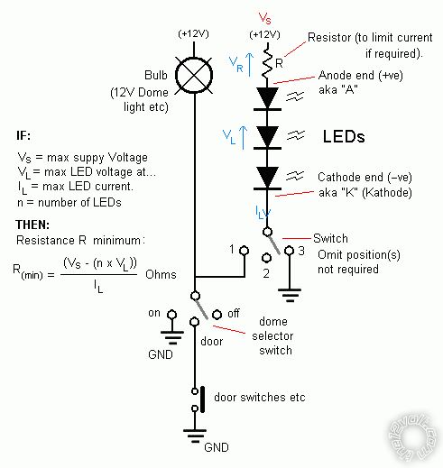
The resistor depends - its minimum size is based on the LED max tolerable voltage & max tolerable current and the maximum supply voltage (say 14.4 - 15V?).
Where n times the max V(LED) exceeds Vs, they should not be required.
Posted By: 97accord
Date Posted: April 28, 2010 at 2:45 AM
k thanks oldspark
another question where does the negative wire's from the led's go to?
also does switch #1 go to the positive wire on the dome line?
Posted By: oldspark
Date Posted: April 28, 2010 at 4:16 AM
None of the switches are connected to the positive wire if by positive wire you mean +12V.
The positive 12V supply is shown by "+12V" in the diagram.
+12V connects to the lamps - whether that be the dome light bulb or the +ve end of the string(s) of LEDs.
The negative end of the LED string(s) goes to GND.
Hence when you have GND at one and and +12V at the other, you have 12V across the lamp(s) (bulbs or LEDs) and they light up.
If you break the connection at one end - in this case with some sort of switching at the negative end - the attached lamp extinguishes. IE - current cannot flow from +12V through the lamp to GND.
Do you understand that in the diagram, the grey "wiper" or arm of the switch(es) is what moves to positions 1, 2 or 3 for the different behaviours?
And that the bottom door switch "closes" to connect thru to GND?
If you want the LEDs to imitate the dome light, or if the LEDs are the dome light, then ignore the RH switch - the LEDs are merely connected between +12V and the dome switch, or door switch depending on what you want.
Posted By: 97accord
Date Posted: April 29, 2010 at 12:28 AM
k thanks
but is the switch that is connected to the led's on the right side slot (1) tap's into the 12v + that goes to the dome light?
Posted By: oldspark
Date Posted: April 29, 2010 at 3:39 AM
Ah - you mean at the top?
Anywhere. +12V is +12V.
Posted By: 97accord
Date Posted: April 29, 2010 at 3:50 AM
so the switch for the led switch their would be a + the + from the dome 12v and the- to the car metal right?
Posted By: oldspark
Date Posted: April 29, 2010 at 4:18 AM
Que?
Which part of any switch is connected to +12V?
Or re-explain what you are asking.....
The diagram should tell you all you need to know about the electrical connections.
How it relates to physical reality is a different issue.
And it will certainly be different if you had +12V switches involved!!
Posted By: 97accord
Date Posted: April 29, 2010 at 4:34 AM
k if you look at you diagram
on the right side of you picture with the led's their is the 3 way switch their their is the (1) with a wire going to the OX drawing on the left do i tap into that wire?
also by doing this do would i need to buy the diodes in order for this to work?...
Posted By: 97accord
Date Posted: April 29, 2010 at 4:55 AM
also would i need the diodes in between each led's or i would just need one in n out?
Posted By: oldspark
Date Posted: April 29, 2010 at 5:21 AM
The LEDs are the diodes. Remember those lighting rods from page 1?
You tap into the wires as shown on the diagram.
Do not tap into your left hand indicator because that is not shown on the diagram.
Do do tap the GND to the +12V because not only is that not shown on the diagram, but is highly unrecommended by many on this forum.
Also if a switch is connected between +12V and GND, I strongly advise having the O & X somewhere in between (we call X&O a "light bulb" or "lamp"; O&X is the same connected back to front) and/else the LEDs if you prefer (ie - a 12V LED string etc).
Hopefully you understand the above principles.
BTW - call it a hunch, but are you having difficulty understanding wiring diagrams?
Or is it just the way I draw mine?
Maybe instead you can post the drawing that describes your present dome light & LED wiring? I could then modify that.
Posted By: 97accord
Date Posted: April 30, 2010 at 4:32 AM
i kinda understand it
it just that your not understand what i am telling you...but i do appreciate your help
the led(s) switch (1) is that a negative wire that is going to be tapped into the dome 12V wire?
also for all the led(s) wire(s) the (4) positive can i twiste them all up and run one wire to the car battery
and all 4 of the led(s) negative wires will be twisted up and run one wire to the led(s) (2)switch terminal
.....
is this all right?.......i'll try an c if i can post a picture for you asap
Posted By: oldspark
Date Posted: April 30, 2010 at 5:17 AM
It's only your questions I don't understand - I do understand what your are telling me.
Post the drawing.
Posted By: 97accord
Date Posted: May 01, 2010 at 1:00 AM
hey oldspark im working on the picture
i was just wondering if i am adding 4 led(s)..would i need to put a fuse in between to 12V source and the led(s)...if so would you happen to know how much amp fuse would i need?
Posted By: oldspark
Date Posted: May 01, 2010 at 4:03 AM
Only a fuse to protect the wiring if it isn't already there.
There is no point using a fuse to protect the LEDs. (A resistor is better if that is used.)
|