parallel constant current source drivers
Printed From: the12volt.com
Forum Name: Lights, Neon, LEDs, HIDs
Forum Discription: Under Car Lighting, Strobe Lights, Fog Lights, Headlights, HIDs, DRL, Tail Lights, Brake Lights, Dashboard Lights, WigWag, etc.
URL: https://www.the12volt.com/installbay/forum_posts.asp?tid=120332
Printed Date: March 20, 2026 at 8:48 AM
Topic: parallel constant current source drivers
Posted By: sallc5
Subject: parallel constant current source drivers
Date Posted: February 23, 2010 at 6:30 PM
I am designing an LED array for a tail lamp assembly.
I have decided I want to use constant-current drivers to set the current for each LED string.
I am going to have the tail lamps on at .25-.50 (5mA-10mA) brightness and the brakes/turn signals illuminate at 100% (20mA) brightness.
The tails and stop/turn arrays will be separate arrays but combine to make one when the stop/turn signal is applied.
My question is instead of having the tail LEDs remain on at .25-.50 brightness when the stop/turn signal is applied, how would I have the tails illuminate from .25-.50 (5mA-10mA) to 100% brightness when the stop/turn signal is applied.
I figure I can use two constant current sources drivers in parallel. I am not sure on how to do this though.
If anyone can provide some in sight or an alternative (better? more efficient?) way to accomplish this I am all ears.
Any numbers I used are purely for speculation as I have not decided what size/type of LEDs I will be using.
I did see some LED tails/stop/turn threads but none so detailed.
Thanks in advance!
Replies:
Posted By: oldspark
Date Posted: February 24, 2010 at 5:32 AM
The stop power merely bypasses the smaller current limiter.
EG - Assume 3x3.4V LEDs, the first const-current is (say) 5mA & the 2nd is 20mA followed by the 3 LEDs.
Tail goes to the top of the string hence the 5ma limit.
Stop powers the top of the 20mA (bypasses the 5mA limit).
Further refinement depends on the current limiter circuit - ie, whether a resistor etc can be bridged or shorted by the stop or tail signal
Posted By: sallc5
Date Posted: February 24, 2010 at 1:05 PM
Oh you again? Haha just kiddin! Thanks for the input.
I have been contemplating using a TLE4241GM. Which is made for exactly this purpose. here is the [url=https://www.infineon.com/dgdl/TLE4241_DS_13%5B1%5D.pdf?folderId=db3a30431400ef68011421b54e2e0564&fileId=db3a30431ddc9372011ebaad49bf7f26]data sheet.
I am still new to all this so, could you explain to me how I would go about wiring this up? I diagram would be superb.
TIA!
Posted By: oldspark
Date Posted: February 24, 2010 at 5:03 PM
I was thinking of current limiters like:
[from vidisonic.com/2008/07/10/current-limiting-circuit/}
But with those TLE4241 I guess you could have as many as desired paralleled and controlled by a PWM that alternates between 2 duty cycles if the TLE4241 output current can go enough.
How did you go with brightness comparisons and resistors?
What current gives you a good taillight dimness? (I assume ~20mA for brakes.)
Why not simply bridge out the resistor for brake lights.
IE - each string has its common resistor at one end.
The extra dimming resistor is at the other end.
The brake signal shorts out (bypasses) the extra dimming resistor.
The common resistor may be at the ground end with the dimming resistor at the +12V (tail power) end. The brake +12V signal connects between the dimming resistor and its LED - through a diode if your are doing it on a per-string basis.
PS - I re-read your OP. I suggest you get some sample LEDs. And also contemplate why you do NOT want a simple resistor (bridging) circuit (or why you want it some complicated?)?
Posted By: KPierson
Date Posted: February 24, 2010 at 6:24 PM
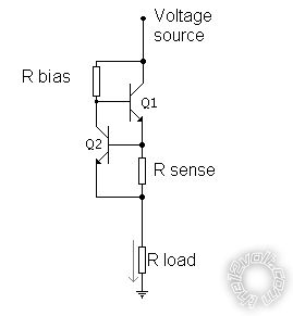
I personally don't think I would go this route, but I'm not sure without lots of testing. Anyway, here is how I think it would hook up: 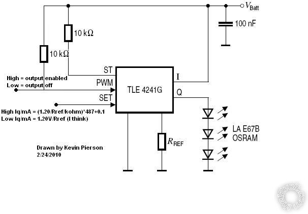
My big issue is that is shows the LEDs wired in series where I would think they would wire in parallel. I also feel, that in your case, at least, that you can get comprable results from using a 5vdc regulator and precision resistors to limit the current of each LED. I would use one resistor per LED so that if one goes out the rest remain active. In the above drawing if an LED opens up your whole strand is gone! Not too cool in a brake light, tail light, or turn signal application. The above chip would be beneficial when using a processor and error detection is critical (ie burned out taillight indicator). Are these going to be used on a street vehicle? If so, don't forget the DOT approval process to make them legal! ------------- Kevin Pierson
Posted By: oldspark
Date Posted: February 25, 2010 at 5:56 AM
The 3 in series is ok (3x3.4V = 10.2V etc)
And it's one circuit per string (ie, or 3, or 4, LEDs).
And I saw that the PWM isn't needed - it can be done by the R-ref resistor (as drawn bottom RH of the TLE424; I didn't check the SET options).
But how do you change or short out parallel R-refs? (Is PWM the solution?)
I still reckon resistors that are bypassed with the brake signal via diodes.....
Posted By: KPierson
Date Posted: February 25, 2010 at 6:38 AM
yeah, I'm just not a big fan of running any LEDs in series, especially in critical tasks like this. From an original design perspective it makes more sense to just parallel them all. I'm also concerned that they arn't showing any parallel LEDs which, to me at least, hints that paralleling the output may not work very well. I'm not sure why it wouldn't, but you would think they would at least show it on the datasheet. If you take the "set" line high it internally amplifies the current output by the formula given in the datasheet. This 'may' provide adequate results, but I don't like the lack of control over the level of amplification. You would almost be better off changing the Rref value instead of messing with the "set" line. All the more reason to not use it! ------------- Kevin Pierson
Posted By: oldspark
Date Posted: February 25, 2010 at 5:41 PM
No problems with 3 or 4 LEDs in series. Are you thinking of longer strings?
And if it is current limited, there is no problem whatsoever - LED string issues are to do more with simple resistive current limiting. (Ignoring a single LED or connection failure - but there will be the other parallel strings.)
But this project elsewhere mentioned a somewhat large number of LEDs - reducing the parallel cost threefold IMO would be worthwhile!
Although that device can supply 83mA, 4 strings could be paralleld, but that IMO defeats the purpose of using it!
Hence I assumed once TLE per string. Of 3 times as many for single-LED strings.
We both seem to be against the use of this TLE device.
The only advantage I can see is to be able to run an independent PWM to all the parallel LED strings and modulate or vary the brightness as desired. But one 8-pin chip per string of LEDs etc etc..... for this? Not in my book.
Hence my question above - what are the 2 currents desired - one is presumably 20mA; what is the other?
|