Vehicle Lights Wiring From Scratch
Printed From: the12volt.com
Forum Name: Lights, Neon, LEDs, HIDs
Forum Discription: Under Car Lighting, Strobe Lights, Fog Lights, Headlights, HIDs, DRL, Tail Lights, Brake Lights, Dashboard Lights, WigWag, etc.
URL: https://www.the12volt.com/installbay/forum_posts.asp?tid=124110
Printed Date: March 23, 2026 at 6:06 AM
Topic: Vehicle Lights Wiring From Scratch
Posted By: rbflip
Subject: Vehicle Lights Wiring From Scratch
Date Posted: October 24, 2010 at 6:44 PM
Hello,
I am starting a wiring project from scratch and well, wiring is a very weak subject for me, hopefully someone will be able to point me in the right direction.
I need to wire Headlights, running lights, blinkers, brake lights, brake light switch and gauge lights.
headlight switch is a On-off-On
blinker switch is a On-off-On
LED rear with 3 wires = white=ground, Red=Tail, black=Stop&Turn
front running lights are regular auto bulbs.
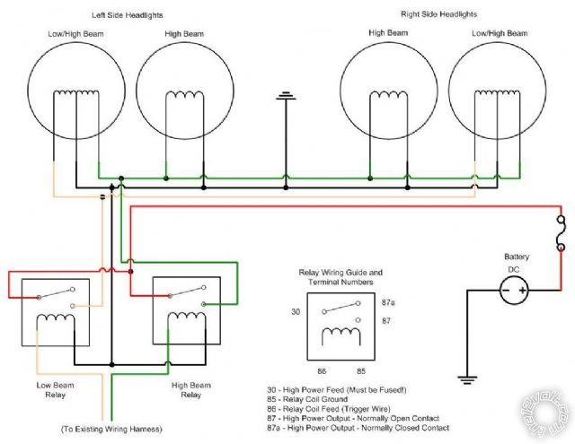
I have 4 SPDT relays and 2 DPDT relays in my possession right now, I was able to get the headlights to work following this diagram, skipping the 2nd headlight as there is only one.
I have tried the tail, brake and blinkers but just cannot get it figured out. If I have left something out please let me know.
Thanks,
Ryan
Replies:
Posted By: oldspark
Date Posted: October 24, 2010 at 7:41 PM
The above is fine provided the high & low are "exclusive-OR" - ie, one OR the other, but not both.
Hence the yellow & green to the existing harness comes from a +12V SPDT switch.
You need a switch for the other lights.
Normally a headlight switch is off, then on for parkers/running lights, then on for beams as well as parkers/running lights.
The beams then go to an SPDT for hi or lo beam selection.
They are usually dual-pole switches, but a normal off-on-on switch can be used with a diode from the "beam on" to the "parkers on" middle position (so that the parkers/running are on whenever the beams are on. Usually a relay for the parkers/running lights would be used so that the switch & diode only needs to energise the the relay(s) - ie, under 1A.
Posted By: rbflip
Date Posted: October 24, 2010 at 8:08 PM
thank you for the info, I guess I am back at square one :) If anybody has any diagrams on how i might wire up the tail,brake,brake light, blinkers, park and headlights It would be much appreciated, I am a visual person and the wiring is my weakest subject.
The vehicle is a 89 Jeep YJ but all the wiring is gone and is being run from scratch
Thanks,
Ryan
Posted By: Ween
Date Posted: October 24, 2010 at 10:57 PM
does the steering column still have the turn signal and hazard switch(es) attached? is that wiring intact, wires coming out of the column itself? i'd use separate fuses for the battery feeds for the low and high beam relays, if for whatever reason one shorts out, you'd still have headlamps. or use circuit breakers.
mark
Posted By: oldspark
Date Posted: October 25, 2010 at 12:11 AM
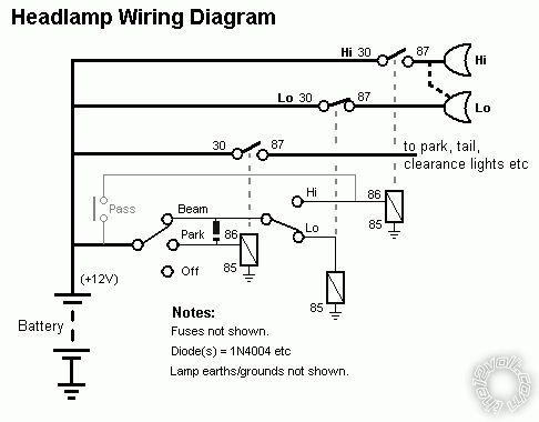
Below is a simple wiring diagram based on my earlier description....
Posted By: rbflip
Date Posted: October 25, 2010 at 10:33 AM
thank you for the information. The steering column is gone, this is really from scratch, no original gauges or switches are present.
thank you for the headlamp diagram, I will look over some more and see if I understand exactly what is going on and try to implement on the bench.
thanks,
Ryan
Posted By: oldspark
Date Posted: October 25, 2010 at 5:38 PM
Keep in mind there are many ways to wire lights etc.
If using common non-automotive switches (ie, low current), then relays are used. (Though IMO that is essential for headlights anyhow.)
And diodes to make up for switch logic (ie, dual-pole, changeover, OR, AND).
The sense logic can change too - eg, a switch might ground the relay coil.
(Though I usually prefer hot power switching - ie, +12V is switched to the lights - not GND.)
But especially for lighting, I believe each beam (hi/low) should have its own on/off relay - not a change-over relay to select them.
Both systems require 2 relays, but with the changeover relay method you can have total failure or one-beam failure if one relay fails. (With separate relays, only one beam will fail, and you can swap relays to have your beam of choice.)
My previous diagram shows the "simple" SPST relay method.
It lends itself to easy modification - eg, 4 headlight systems where low-beam is always low (the dip or flash switch merely becomes and on-off for the high beam), or separate beam fusing, different power (fuse) sources, and individual relays.
BTW - I converted my ancient pre-millennium vehicle to circuit breakers for the lights.
When I think about it, not using non-resetting breakers for headlights is insane! (My original vehicles have ONE fuse for ALL lighting. Even before circuit breakers became common, I split that to alternate power paths and fuses.)
Posted By: rbflip
Date Posted: October 25, 2010 at 6:01 PM
thank you for the info, I am having difficulty sourcing a off-on-on switch at the moment, I only have on-off-on in my possession, if you know of a place to source a off-on-on switch on the internet please let me know. Once I can get this working i need to tie in blinkers and brake light switch.
Thanks,
Ryan
Posted By: oldspark
Date Posted: October 25, 2010 at 6:30 PM
I'd suggest the local wreckers.
Even if not using automotive currents, their switches are often the most functional and easiest to mount and interface.
I presume this beast is NOT for road use.
Otherwise off-on-on may have to be an on-on-on.
Or two separate ons - ie, the first powers the parker relay and the 2nd switch for the beam off-on to the dip switch.
Posted By: rbflip
Date Posted: October 25, 2010 at 7:00 PM
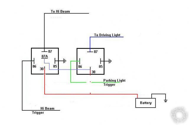
Correct, this is not for road use but must have almost all functionality with regard to lighting. I found this diagram on this site and wired it tonight with what I have and it works, does it look ok? If so how should i wire in the blinkers and brake light for proper functionality?
Thanks again for your help.
Ryan
Posted By: rbflip
Date Posted: October 25, 2010 at 7:01 PM
forgot the diagram.
Posted By: oldspark
Date Posted: October 25, 2010 at 9:25 PM
If it works and you are happy with it, keep it.
It suffers from the SPDT (changeover) failure that I mentioned, but it only uses a high-beam switch (the low beam being on when the park lights are on (assuming hibeam is NOT on and that the hibeam relay (LHS) has not failed).
For other wiring, use the wiring of any car... almost.
Indicators are battery - fuse -(IgnKey)-(fuse)- flasher-can - into a 2-way centre-off switch. Each side goes to the indicator bulbs (+12V).
Brakes are battery - fuse -(IgnKey)-(fuse)- stop-switch - to brake bulbs (+12V).
Whether you wire thru the IgnKeySwitch (or its relay) and have additional circuit fuses is up to you.
|