schematic proof read
Printed From: the12volt.comForum Name: Lights, Neon, LEDs, HIDs
Forum Discription: Under Car Lighting, Strobe Lights, Fog Lights, Headlights, HIDs, DRL, Tail Lights, Brake Lights, Dashboard Lights, WigWag, etc.
URL: https://www.the12volt.com/installbay/forum_posts.asp?tid=128508
Printed Date: May 13, 2026 at 1:31 PM
Topic: schematic proof read
Posted By: --weezl--
Subject: schematic proof read
Date Posted: September 12, 2011 at 8:25 PM
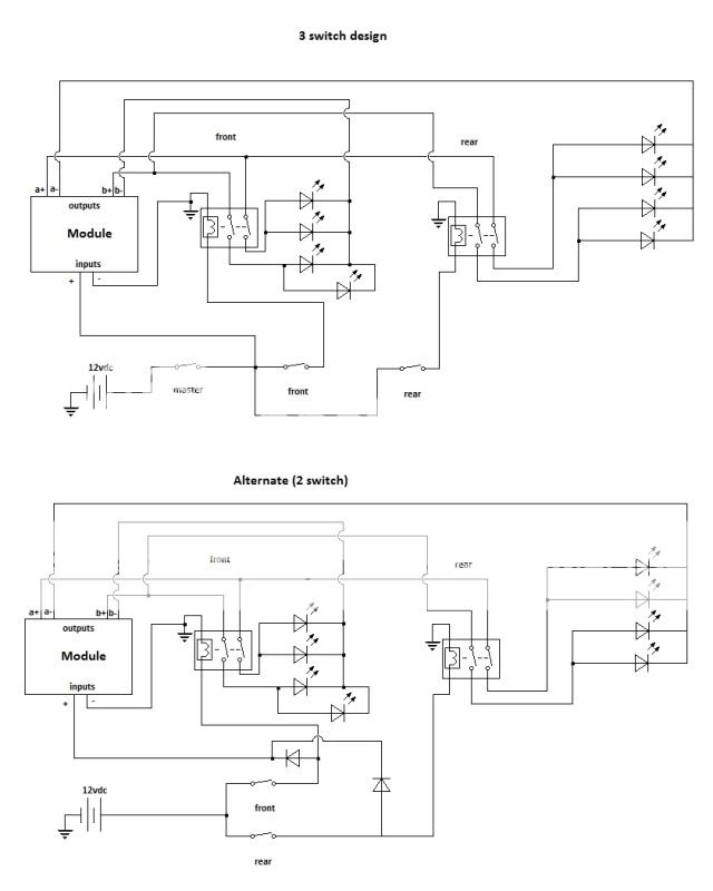
hey, i'm new here, hoping to get a little bit of help on a diagram i drew up today, basically, what i'm doing is wiring my truck up with amber safety lights, the legal aspect has all been taken care of, so no worries there, the product i'm making my own kit out of several random items from different places, the main part that needs to be known to you guys, is the module, for all intents and purposes, the "module" is a wig wag module... if anyone has used this particular one, please let me know what you have found, and if you have used it, please let me know how the 3rd output wire works on the patterns... all of the patterns they show are an a/b system, which would have 2 outputs... idk... here's the schematic though:
now before you ask, the modules aren't all that cheap, so to keep my costs down, i'm using one, but i need to be able to independently control the front and rear of the truck's lights, which is the whole purpose of this schematic... the only thing i think i might have made a mistake on, is the directionality of the diodes (both LED and normal) that is one thing i'm not concerned about, but i think they are in the correct way...

-------------
no signature needed
now before you ask, the modules aren't all that cheap, so to keep my costs down, i'm using one, but i need to be able to independently control the front and rear of the truck's lights, which is the whole purpose of this schematic... the only thing i think i might have made a mistake on, is the directionality of the diodes (both LED and normal) that is one thing i'm not concerned about, but i think they are in the correct way...
-------------
no signature needed
Replies:
Posted By: --weezl--
Date Posted: September 12, 2011 at 8:29 PM
doesn't appear my picture worked... here's a photobucket version...
additionally, the flasher module i'm looking at is this one (i am not promoting the brand at all, merely asking for advice on wiring, and products https://www.ebay.ca/itm/4x-4W-LED-WHITE-Flash-Strobe-Light-Headlight-USA-SELLER-/400225987719?pt=Motors_Car_Truck_Parts_Accessories&hash=item5d2f53ec87
-------------
no signature needed
Posted By: oldspark
Date Posted: September 13, 2011 at 3:43 AM
The diodes look ok, but the power diodes in the alt 2-switch version will have to be high current, else energise a power relay.
I suspect that flash-strobe is christmas-tree lighting circuit.
And handling 26 globes (meaning of the 21W variety) is a lot of LEDs! (IE - a single 12V LED string is typically 0.3W.)
I suspect that flash-strobe is christmas-tree lighting circuit.
And handling 26 globes (meaning of the 21W variety) is a lot of LEDs! (IE - a single 12V LED string is typically 0.3W.)
Posted By: --weezl--
Date Posted: September 13, 2011 at 11:47 AM
Thanks for the reply, the module I'm using is designed to run 27 4w led headlight bulbs.
Is there a simpler or better way to wire this up, that you can see at all?
Thanks for the reply btw!
-------------
no signature needed
Is there a simpler or better way to wire this up, that you can see at all?
Thanks for the reply btw!
-------------
no signature needed
Posted By: oldspark
Date Posted: September 13, 2011 at 1:23 PM
Better? There are several options depending on preference - ie, using DPST switches instead of relays, though I prefer relays - especially if they are high current (~10A etc) or remote.
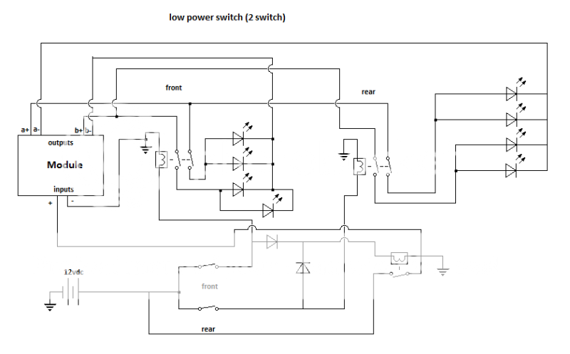
I reckon the lower diagram with ordinary diodes (IN4004 etc) from the front & rear switches that energise an SPST relay to provide power to the module input+.
And a fuse from the battery of course.
PS - actually I don't see the need to switch the -ve (else +ve) of the LEDs - hence just SPST relays.
I reckon the lower diagram with ordinary diodes (IN4004 etc) from the front & rear switches that energise an SPST relay to provide power to the module input+.
And a fuse from the battery of course.
PS - actually I don't see the need to switch the -ve (else +ve) of the LEDs - hence just SPST relays.
Posted By: --weezl--
Date Posted: September 15, 2011 at 11:27 PM
oldspark, i'm not quite following you there... basically, there are 4 wires from the module, that are going to the front leds, 2 for each set of leds, these 2 sets MUST be on separate circuits, otherwise i won't get the wigwag pattern that the module provides (among other patterns) so i would need 2 spst relays, per side, 4 total, for the 4 separately controlled lights (either controlled by me, or the module)
the switches i'm using are a 2 position on-on push button dpst switch, with LED indicator, (8 leads on the back)and i already have them, and i'm currently working on the bezel they will sit into, have about 10 hours into it so far, made out of polycarbonate...
what a friend of mine suggested, which i might look into down the road, is a 4 position switch, off, front, back, front & back... though i don't really like that idea as much as the 2 separate switches... the 3 individual switches seems a little cumbersome, the more i think about it, and takes up an unnecessary switch location, which i am sure i can find a use for...
as it is i've got locations for 5 switches, 1 will be for my ABS cancel, 2 will be for these lights, and 1 will be for my driving lights (2, big ass 100 watt halogens in the grill)
-------------
no signature needed
Posted By: oldspark
Date Posted: September 16, 2011 at 12:58 AM
idiot oldspark who wishes to withdraw his former wrote:WITHDRAWN!!! See "FYI - my former reply opening:" below for a laugh!
PS - actually I don't see the need to switch the -ve (else +ve) of the LEDs - hence just SPST relays.
As to your switches, in your case I'd say stick with it (with 10 hours work... It's always the "simple" harware fitment that takes eons!).
But in ANY case, I too prefer 2 switches rather than a 4-position switch. IMO - that is good design. [IE - simpler, independent, still half a circuit if one switch fails, and usually no need to check which position the switches are in (especially if paddle switches, ie - if not direcly looking). That's unless space was at a premium.]
With the 3rd switch, I think powering off the 2 existing switches is better AND easy - just the 2 diodes and an extra SPST relay. I prefer relays to switches anyhow if switching above a few Amps.
Using your lower diagram, the two power diodes between the switches and the module's +12V supply (input) can be reduced to small diodes (eg, common 1A 1N400x series - IN4004 etc, instead of BIG diodes to handle the full module current, though they can also be used), and connected to the extra relay's coil (86, with 85 to GND). Its contacts (30 & 87) are inserted between the module + input and the batery supply to the switches.
IE - the diodes power the relay coil. The +12V module input is connected to 87 and its power (30) is takne from the switch +12V input.
And the lot shoud be protected by a fuse (or maybe self-resetting ciruit breaker; ~$8 for up to 50A capacity) between from the battery +12V.
Actually the last is merely a conversion from using high-current diodes to low-current diodes and a relay. That is often used for polarity protection - eg, car EMS, and any system that is at risk from incorrect polarity connections.
So, other than my last "big to small" diode conversion, I have done nothing to change your 2nd/lower diagram (which IMO is by far the preferred solution. If curcuit isolation is ever required, simply pull the (not shown) fuse).
FYI - my former reply opening:
Yes, they are on 2 separate circuits. Hence only 2 breaks are required - not 4 as you have. Different if they were mutliplexed, but that's a totally different solution anyhow. I thought I may have misread your diagram(s), but no - I think I'm still consistently sane (or insane). To simplify in the active/closed circuit... No, YOU ARE RIGHT. It is "4 circuits" - they are multiplexed - each b outout goes to each a output.
See - even idiots like me get (very) confused and get things wrong.
It also shows (IMO) the need for a scribble pad sketch rather than a "head redraw" - though why my first 2 head jobs didn't work but the 3rd did (so to speak...) leaves me in my usual state of bewiderment.
& Hey - thanks! New name proposal - idiots like me - that could end my jealousy directed at i am an idiot. Though others hereon might take offence...
Posted By: --weezl--
Date Posted: September 17, 2011 at 3:11 AM
lol, ok, so you are thinking something like this (with the spst relay) i was originally thinking you meany use spst instead of the dpst relays! lol
ok, additional question, i want the brake lights to flash along with the led strobes, so here's the situation i'm thinking is going to come up, right now, none of this hardware, except for the top switch exists, it's all new parts that are going to be coming... i'm also not sure if it is a switched ground, or switched positive... i have a set here right now that are a switched ground, which makes me worry a little...
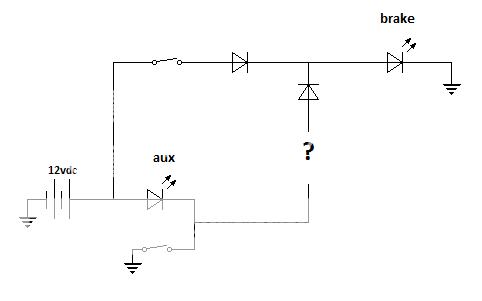
essentially, the aux light should be looked at as an LED strobe, and i want the brake light to strobe on, at the same time as the aux (not an issue if the brakes over ride it)
this same problem persists with my reverse lights, with how i want to wire them up... what do i put in place of the question mark, that will be able to keep up with the fast strobing? i could use a NO relay with constant power, but i can't see the relay lasting very long with the strobing effect...
-------------
no signature needed
ok, additional question, i want the brake lights to flash along with the led strobes, so here's the situation i'm thinking is going to come up, right now, none of this hardware, except for the top switch exists, it's all new parts that are going to be coming... i'm also not sure if it is a switched ground, or switched positive... i have a set here right now that are a switched ground, which makes me worry a little...
essentially, the aux light should be looked at as an LED strobe, and i want the brake light to strobe on, at the same time as the aux (not an issue if the brakes over ride it)
this same problem persists with my reverse lights, with how i want to wire them up... what do i put in place of the question mark, that will be able to keep up with the fast strobing? i could use a NO relay with constant power, but i can't see the relay lasting very long with the strobing effect...
-------------
no signature needed
Posted By: --weezl--
Date Posted: September 17, 2011 at 3:13 AM
should have mentioned, that when this project gets done, every light on the exterior of the truck, will be LED, so there won't be any issues with bulbs not keeping up with the flashing, or burning out or anything...
-------------
no signature needed
-------------
no signature needed
Posted By: --weezl--
Date Posted: September 17, 2011 at 3:43 AM
sorry to keep posting, by my math, the entire setup, should be drawing about 2.8a on the lights, maybe another .5 on the module, so 3.3 amps?
if i were to do it completely relay-less, i would need 2 tpst switches, wouldn't i? do they even make triple pole switches?
i think with the relitvely low current draw, (3.3 amps or so) i should be good with just the 2 relays, 2 switches, 2 power diodes... the switches i have are rated at 3a 220vac, but the LED in them is 12vdc...
not to mention there will never be that full 3.3 amps running through the switch at one time... though i don't know exactly what my tail lights draw... i could look that up though... i know it's less than stock, because they come with load equalizers...
front would be... 24w, so 2a, and the rear has about 10-11 plus the brake lights... lets say high side, brake lights are 7w each, 25ish w on the back, so another 2 amps or so... each switch would only be looking at a 2 amp load, which should be well within range, not to mention these switches SHOULD have a safety factor, right?
-------------
no signature needed
Posted By: oldspark
Date Posted: September 18, 2011 at 7:06 AM
Yep - that top diagram is fine - with a fuse at the battery.
The strobed brake lights get tricky because of the multiplexed module output. It's be easy if they were common GND else +12V.
But using a relay or transistor to strobe them may be ok.
A relay is ok if the flash rate is not too fast.
Otherwise a transistor or MOSFET which is simpler if the brake lights are GND switched - the switcher (transistor, MOSFET or relay) then merely connected in parallel with the brake switch.
The relay or transistor or MOSFET is energised/driven by whichever of a+ or b+ you want to use, noting a+ & b+ won't be be the same as a particular strobed LED - it might be +12V all the time or whenever a- or b- are "active".
But a- or b- could also be used.
But first need to know whether the brakes are +12V or GND switched, and which module output is the pulsed output - is it (a & b)+ or (a & b)-?
The latter is simply tested by connecting one 12V LED from a+ (or b+) to GND, or the LED from +12V to a- or b-.
That determines whether a more common NPN transistor or N-channel MOSFET is used for the input for the strobed brakes else the less common PNP tranny or P-channel MOSFET.
Similarly for which type is required for the output (power) to the brakes - NPN & N-ch if ground switching, or PNP or P-ch if +12V switched.
If using a relay, the polarity of the input signal (a/b+ or a/b-) is not important (merely ground else +12V connect the other end of its coil), though you must know whether the brakes are GND or +12V switched. Either way it is the same relay (ie, SPST relays are not N-type or P-type), though a transient-protection diode must be used across the relay's coil to protect the module outputs from coil-induced voltage spikes. (Hence by tradition fixing the +ve (86) and -ve (85) ends of the relay coil - the Kathode or line-end of the diode is connected to the +12V end.)
Others hereon are better for opinions on relay speed switching. I do not consider them suitable for fast strobing (eg, police & emergency vehicle strobes), however after recently seeing relays used to switch lights to music, I know they can work - but I don't know how long for (still the normal ~1 million operations?)
Another consideration is incandescent versus LED brake lights.
Each incandescent brake bulb is probably almost 2A (21W) compared to maybe up to 100mA (1.2W) if LEDs. That can impact relay contact life and transistor/MOSFET sizing.
Furthermore, incandescents have thermal inertia and take longer to light up and extinguish than LEDs, plus the thermal fatigue from switching ages the bulbs.
Hence a flashing incandescent might only last hours or days, plus they won't have the crispness of a strobed LED.
And if the strobe pulse is to short, the bulbs may not light fully.
Though those can be overcome (trickle-current resistors to pre-heat bulbs, and RC delays to extend on time), it'd be better to get the LED brake lights.
And don't forget that if you change left-right indicators/flashers to LEDS, you probably need change your flasher can/module. (Some electronic types can be modified - just change the value of its current feedback resistor.)
But don't get those expensive resistor ballasts to solve that issue - that undoes the "power saving" of the LEDs. (IE - those resistors are the equivalent of the original ~21W incandescent loads that were replaced. In fact I usually recommend using cheaper incandescents instead....)
As to a 3pst switch... WOT? And undo all that switch work?
But you might be right, and they do exist. But I would still prefer your 2 switches (cool man!) and relays - hence whether you have 3A or 30A or 300A loads it doesn't matter - ie, the common 30A relay is fine for now. Increase its rating later if you have to, but you'd use the same buttons.
How about a 3p4p switch to go back to a space-saving single switch? Nah - I still prefer 2 switches for earlier reasons (simpler wiring, independent) and no (off-)on-off-on of (say) the rears to get to both (off, rear, front, both).
But in whatever case - relays. That means a greater selection of switches since they probably only need to be rated for 0.5A - 1A.
The only mod I'd envisage over 2 buttons/switches is a 3rd if you want ONE to do both, as well as the existing 2 individuals.
Does that sound appropriate to you? IE - low-power switches to control relays of (say) 30A?
Normally the relays would be outside the cabin to be more inline with the light power wiring, but I presume in this case the strobe module is inside (the cabin), and the (or 2) relays are probably to be on/with the module (unless the on-off clicking noise is problem). But it should still reduce the heavy power wiring to the switches if the module is under-dash (but still suitably accessible for pattern adjustment) - not that 0.5A to 5A wires makes that much difference (I'd probably use 5A wire for both). But later if extending to 30A etc.
Not that I have checked your power/current calculations...
I also hope the strobe module remembers the last pattern chosen between uses...
Posted By: --weezl--
Date Posted: September 19, 2011 at 2:52 PM
you lost me with a LOT of that! lol
the tails/brakes on the truck right now are incandescent, however they will be LED before these go on, i had led's on them, and they got smashed, meeting up with the guy who hit them to get money for them today, ordering off ebay probably in the next 2-3 days, when i figure out exactly what i'm doing...
the strobe speed will be quite fast, they are an emergency light i'm putting on the truck, and i'm 99.9% sure that it's a switched +12v for the brake lights, not switched ground, which i would think makes it slightly easier...
as for the module, i'm planning on putting the module above my rear view mirror, and below the head liner of the truck, it's very small, and i THINK it remembers the last pattern chosen, or i will have to wire it slightly different, maybe hardwire the unit into the battery, then just switch the outputs... depends on where the power switch the module comes with is... i don't remember there being one on the module it's self... but i could be wrong
i was thinking a transistor, because it works similar to a relay, but with no working parts, right?
as for the flasher module (for turn signals) they are already taken care of, i've got an LED replacement in, last week (before i removed the broken LED tails) the only lights on the outside of the truck that were not LED, was my highmount stop light, headlights, fog lights and driving lights (head, fog and driving lights can't be LED, they don't make LED replacement bulbs for them) and the high mount i haven't had a chance to get a new one yet...
what i'm doing:
headlight strobes (1 each side) bar lights in grill (one each side) bar lights in rear door(side) window (1 each side) bar lights in rear window (1 each side) both brake lights (1 each side) and 2 tail light strobes (1 each side)
the grill and side bar lights are 4 watts a piece, the headlight (and tail light) led strobes are 4 w a piece, the rear window bar lights are probably around 2w a piece, and i'm not sure about the tails, can't find any technical specs on them...
though, now that i think about it, there is a load equalizer that comes out the rear of the light, with a plug, if i were to just plug the power and ground wires into the load equalizer plug, would that work? i don't need the load eq, because i've got the LED flasher, and in fact it undoes all of the electronic benefit to having low current LED's in the first place... so i would need to put a diode in so the positive input from the strobes, doesn't feed back into the other brake light, and that the ground from the light doesn't give a positive ground for the strobes...
does this make sense? let me draw a pic, and i'll post it...
-------------
no signature needed
Posted By: --weezl--
Date Posted: September 19, 2011 at 3:05 PM
yeah, the more i draw, the less it makes sense... it worked in my head, but the switched ground wouldn't exist for the strobes, as it would take the solid ground of the normal circuit... if they were both switched ground, i would be golden, or if they are both switched positive i would be golden...
going to be a matter of waiting to see when they show up... for all i know, this kit MIGHT be a switched positive..., in the grand scheme of things, it makes no real difference in the module... it's just where they want to put the switching circuit...
these are the tail lights they are connecting to, btw
https://www.ebay.ca/itm/130574652331?ssPageName=STRK:MEWAX:IT&_trksid=p3984.m1423.l2649

-------------
no signature needed
going to be a matter of waiting to see when they show up... for all i know, this kit MIGHT be a switched positive..., in the grand scheme of things, it makes no real difference in the module... it's just where they want to put the switching circuit...
these are the tail lights they are connecting to, btw
https://www.ebay.ca/itm/130574652331?ssPageName=STRK:MEWAX:IT&_trksid=p3984.m1423.l2649
-------------
no signature needed
Posted By: oldspark
Date Posted: September 19, 2011 at 8:14 PM
Ah - they call it a "load equalizer". What a clever marketing term for a load that uses and wastes as much power as the original bulbs being replaced.
LOL! It's the way they scam extra money out of those that use LEDs for environmental or power reasons. Fit LEDs, Flashers don't work. Buy & fit this. That worked, but now I found out I'm using the same "old" power. Ah - the fit this new flasher module and dump the "load equalizer" we sold you.
And btw, I've been thinking of your truck as an articulated vehicle (heaps of lights down the side). Except for that 4 year old that commented on my "dirty yellow truck", we tend to use trucks as being articulated and not 4WDs nor Hummers etc. [ May that kid see his 5th birthday (sorry, a bad taste thoughtjoke). Damned youngies just haven't learnt NOT to be truthful & forthright! And just because he was 100% correct and I agreed with him is no excuse! ]
Being all LEDs makes it easier.
The simplest would be to DPDT switch them in to the module, else use a transistor or FET.
But I'll re-read and think about it.
And determine if braking is to override the strobed brake lights. (Maybe you stated that above; otherwise yes, no, don't care, or only if driving? (Though the latter should be an alarm that you are driving with strobing lights - assuming that is illegal).)
Thanks for fitting all LEDs up front!
Till later...
Posted By: --weezl--
Date Posted: September 20, 2011 at 7:46 PM
man, you are good at confusing me...
don't need a buzzer at all, it will be obvious enough they are all on when they are on, there are laws to me driving with them on, i know them, i'll follow them... i'm also going to have lights inside the truck to indicate the lights are on (wired into the switches)
and i don't want it so that the brake lights DON'T work, when the strobes are on... i hear what you're saying about the DPDT relay, which would work... except that would cause the directly above situation...
-------------
no signature needed
Posted By: --weezl--
Date Posted: September 20, 2011 at 7:47 PM
i think i'm just going to not worry about that at this point, and hope they come in with a switched positive! lol
-------------
no signature needed
-------------
no signature needed
Posted By: oldspark
Date Posted: September 20, 2011 at 8:19 PM
The brake override is easier.
Then it is just diode-ORing the 2 sources - ie, from module +ve output (via switch) via diode, and brake switch +ve output via diode - to the +12V of the brake LEDs.
Then it is just diode-ORing the 2 sources - ie, from module +ve output (via switch) via diode, and brake switch +ve output via diode - to the +12V of the brake LEDs.
Posted By: --weezl--
Date Posted: May 17, 2012 at 8:32 PM
oldspark wrote:
The brake override is easier.
Then it is just diode-ORing the 2 sources - ie, from module +ve output (via switch) via diode, and brake switch +ve output via diode - to the +12V of the brake LEDs.
hey, sorry i've disappeared for a while, been busy with old jobs and new jobs and trying to keep busy, and moving to a new place and all that jazz!
you lost me here... this changes it from a switched positive to a switched ground right? i hate to be a pain, but can you draw that out for me? it makes more sense when it's in schematic form for me
i still haven't gotten any closer to actually buying or installing all of this, other than the switch mounting thing is all done and sitting in my garage, ready to go in, for when ever i have this all wired up and such... but i've got a few things ahead of it... HAM radio first, which is what is going to get me a viable excuse for putting the lights in, not that i don't already have one...
-------------
no signature needed
Posted By: oldspark
Date Posted: May 17, 2012 at 10:26 PM
It's like the following....
Where the lower "positive triggers" are the input +12V from your flasher or switches etc, and the "to alarm..." is the output to the +12V end of the LEDs.
Hence the LEDs are on if one OR the other input is +12V.
The other way that can be done WITHOUT diodes is if the inputs are GND switching - then join the inputs and connect between LED- and GND with LED+ to +12V.
Posted By: --weezl--
Date Posted: May 18, 2012 at 12:03 AM
that way is both brake on truck is switched positive (which i am about 99.9% sure it is) and the flasher is also switched positive right?
in which case, that schematic, the brown would be where the actual light goes, and the green would be the flasher, and the blue would be the brake wire
it's the other way, where the truck is switched positive and the flasher is switched ground that has me confused...
-------------
no signature needed
Posted By: oldspark
Date Posted: May 18, 2012 at 2:40 AM
Then you have to invert one of them - probably with a relay - and probably the truck (especially if the flasher is load dependent).
Posted By: --weezl--
Date Posted: May 19, 2012 at 3:26 AM
no, the flashers aren't load dependent... that just gets back to the worry about the durability of the relay with that many cycles... how would i use a transistor to invert it?
-------------
no signature needed
-------------
no signature needed
Posted By: oldspark
Date Posted: May 19, 2012 at 10:42 PM
Why worry about the relay cycles - isn't a life if 0.1 to 1 million enough?
Flasher cans use relays though some are thermo-electric types (for the timing). Only modern LED flashers are likely to use transistors etc.
But rethinking this, since you have 2 power sources - namely the strobe & the brake - both will have to be +ve switched and joined through diodes to LED +ve.
Note that if the strobes do use 2 +ve feeds & 2 gnd feeds for their flashing, that's a different solution - eg, the brake circuit causes all LEDs to connect wired to +12V & GND. I lost track of what devices you were going to use, and their specs.
Posted By: --weezl--
Date Posted: May 20, 2012 at 10:38 PM
At this point, I've now emailed the manufacture asking if it is switched positive or switched ground, hopefully all will be simple and only need a few diodes... We shall see though!
Also, I've replaced the thermo-electric flasher with an led type, so monkeying around with that won't change anything...
Though I would personally be a little weary of cutting the stock wiring up to put the relay in there... I don't trust myself enough to do that...
-------------
no signature needed
Posted By: oldspark
Date Posted: May 20, 2012 at 11:25 PM
If you're talking about the strobe module, that's both...
But you shouldn't have to cut stock wiring, Things like this are usually add-ons.
But you shouldn't have to cut stock wiring, Things like this are usually add-ons.