bulb out indicator
Printed From: the12volt.com
Forum Name: Lights, Neon, LEDs, HIDs
Forum Discription: Under Car Lighting, Strobe Lights, Fog Lights, Headlights, HIDs, DRL, Tail Lights, Brake Lights, Dashboard Lights, WigWag, etc.
URL: https://www.the12volt.com/installbay/forum_posts.asp?tid=129257
Printed Date: April 05, 2026 at 1:35 PM
Topic: bulb out indicator
Posted By: urhottboy85
Subject: bulb out indicator
Date Posted: November 16, 2011 at 9:37 PM
I'm trying to find a diagram for wiring an led to my taillights so that I know when one of the bulbs burned out...I can't seen to find any anywhere but I know it had to do with resistors and relays...all the luxery cars come with this already but I have a 05 jeep and wanted to install this in..just need the diagram help...thanks
Replies:
Posted By: oldspark
Date Posted: November 17, 2011 at 1:13 AM
It's a current sensing circuit.
Traditionally done with a resistor in series with the filament(s) to create at least a 0.6V drop with normal current.
That 0.6-0.7V is used to turn on a transistor which STOPS the indicator (LED) from lighting.
If a filament blows, the less than 0.6V (eg, 0.3V or 0V) does not turn on the transistor and hence the LED is lit by the 12V applied to the filaments (whether parkers or brakes etc).
These days chips like Op-Amps or Comparators can be used to sense lower voltage drops - hence a smaller resistor without the large Wattage rating , ie, 0.6V @ 7W for a single tail filament means ~0.6V x ~ 0.5A => a 1./2W resistor, but 2 tails means a 2W resistor, and a brake filament (23W => ~1.75A = 1.1W, hence...) requires a 2W resistor, or 5W for two filaments.
The "logic" is done by extra components - eg, if +12V and NOT > 0.6V, turn the LED on, though the comparator (or op-amp) can do it in one go by an appropriate resistive voltage divider to each input (ie, if voltage on the non-inverting input exceeds the inverting input, then turn the output on). {hey - there's another PICAXE prohject!)
For LEDs, relays are not required as most chips etc can sink or source the ~20mA required for the LED.
And I'm hoping I got the above "designs" correct. It's been a while, and until knowing what current(s) and whether it's +12V or the rarer ground switching to turn on the lights, I'm not spurred enough to check my logic or search (google) for circuits.
But essentially it is a current sensing circuit that turn on a LED when the lamp is on and the current is BELOW the normal total circuit current.
Posted By: urhottboy85
Date Posted: November 17, 2011 at 1:38 AM
So on a comparator would all the legs be positive? And you would just line them up across from each other for which led goes to what bulb then ground each led? Radio shack has a 14 point comparator...so would that be good for 7 lights or would it depend on how its wired
Posted By: oldspark
Date Posted: November 17, 2011 at 2:09 AM
I'm just talking about 2-input comparators. They exist in single, dual or quad versions in chips (ICs, aka Integrated Circuits).
I'd prefer a system that tells me at least which side is faulty (because if it is the near-side, down here it does not make the car unroadworthy wrt on-the-spot fines or defect notices).
And if it's dual filaments per side or "central only" as on a motorbike, I'd like to know if one or both are out. (Same reason, plus safety.)
But some cars simply let you know that a tail (or brake) light is out, and some are happy enough with that.
I recall old Volvos with a single "bulb out" indicator which signal any number of running or park bulbs etc.
So the "resolution" is up to you.
And if that 14-point comparator can be configured for a single reference (ie, +12V to the bulbs) plus 1 to 13 sensors and indicate appropriately, then yes it would be suitable if that's what you want.
And maybe that comparator is a programmable PIC etc so you can mix stop and tail and running lights...
And yes, relative to 0V (ground), all the sensed voltages MUST be positive. The current sensing could output (say) from 0.2V to 0.6V and above - or 0.2V or 0.6V or more down from the +12V - depending on which side of the bulb(s) you put the sensing.
With a smart system, you could even use one current sensor for multiple bulbs.
Posted By: urhottboy85
Date Posted: November 17, 2011 at 4:04 AM
So basically I couldn't use just a comparator them since they are already built into circuits? I can't take just a comparator by itself and plug in the positives to one side and the positive output to the opposite right across from the input?...so basically the comparators are useless unless you have a circuit they are built on to noticed the difference
Posted By: oldspark
Date Posted: November 17, 2011 at 8:00 AM
Yes you can.
A "comparator" can be a basic building block - eg, an IC.
But you can't just connect it to 2 voltages and expect it to know what to do.
You must set up appropriate circuitry (eg, 4 resistors) to convert your two "sampled" or compared voltages so that when one exceeds the other, the comparator switches (the LED on) to let you know there is a fault.
Posted By: urhottboy85
Date Posted: November 17, 2011 at 8:37 PM
Can you put together a diagram or something for me to go off of?
Posted By: oldspark
Date Posted: November 18, 2011 at 6:26 PM
Alas I haven't yet recovered my recently lost data...
But from Linear Technology's Application Note AN-105 - Current Sense Circuit Collection (December 2005), under "Fault Sensing-2" on page 64, "Lamp Outage Detector":
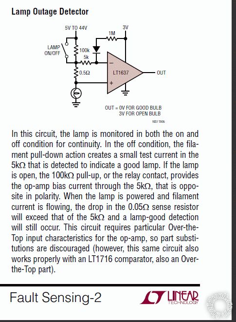
(No Copyright, but thanks to Linear Technology & Tim Regan. IMO a great publication!)
That's just an example using a "high spec" comparator, but it is unusual in that is does includes the switching logic.
Usually it is the lamp switch that supplies the power to the lamp AND the detection circuit. Hence the detection is only active when the lamp should be on - ie, the bad brake-light LED(s) only light when the brake is applied (assuming the brake switch works LOL).
Refer also to Bristolwatch's Voltage Comparator Information And Circuits which is credited to Rob Paisley's Model Railroad & Misc. Electronics page. (Now that's a source I have used before...!  )
In particular see the "Comparator Operation" section a few screens down. That summarises the input-output relationship, noting that the leftside RV variable resistor (aka pot) is equivalent to an upper and lower resistor as shown for the rightside V-Reference "voltage divider". That was what I meant by "scaling" using 4 resistors - 2 for each input, though one would include a trimpot (variable resistor) for calibration.
Also Rob Paisley is referring to the LM339 and similar Comparators only.
The LM339 is very common and is liked because it uses a single supply, comes in a quad package (4 comparators in one $2 14-pin package), and is an Open-Collector output.
That means you don't have to mess with dual or balanced supplies (ie, +6V, 0V & -6V), and outputs can be directly tied together to make an OR circuit (ie, output LED is on if stop-left is bad OR stop-right is bad OR park-left is bad Or ... etc etc.) - often called Wired-OR logic or circuitry.
[ Open Collector outputs - often called ground switching outputs - are the normal inter-connection technique for digital/computer components, alarm sensors or outputs, ignition systems (eg, points and ignitors), and where systems with different supply voltages require interconnecting. ]
Maybe the type of circuit shown under Bristolwatch/Paisley's "Voltage Window Detector Circuit" (nearly halfway thru the html page) is what you want?
BTW - OpAmps can be used. Comparators are merely OpAmps that are preconfigured as comparators, hence avoiding extra circuitry - and often the requirement or confusion with dual-supply OpAmps.
Posted By: oldspark
Date Posted: November 21, 2011 at 12:56 AM
Last night I played around with some rough designs.
Figured a 0.47 Ohm 1/2W resistor in series with a 7W bulb, and a 10k pot - and was it a 27k(?) resistor.
23W would be a ~.15 Ohm 2W resistor in series with the bulb.
A single LM339 quad-comparator package could hence monitor 4 bulbs.
What size and number are you looking at?
Posted By: urhottboy85
Date Posted: November 22, 2011 at 1:19 AM
I was thinking of all the back lights except for the third brake seeing as how t
hats not needed...so 6?..well d should be good since reverse lights are not used as much
Posted By: oldspark
Date Posted: November 22, 2011 at 2:49 AM
Or 3 if you want to sense pairs. Or - with one quad-comparator, 2 pairs and 2 singles.
Posted By: urhottboy85
Date Posted: November 22, 2011 at 7:01 AM
I couldn't do pairs though...cuz if it senses one goes out before the other then it will let me know that a light is out..is rather have 6 leds...the 2 tail light always on and the 2 trail light always on/brake/turn...so that would be 2 single and 2 dual filament
Posted By: oldspark
Date Posted: November 22, 2011 at 7:27 AM
"Pairs" meaning a pair of tails, a pair of brakes etc - not a pair of filaments in a single bulb.
It's too difficult discriminating a 7A or 23W outage from a &W + 23W combination.
Pairs may still be fine - especially when pairs of bulbs on one side (ie, dual-bulb tail or stop lights).
Knowing otherwise exactly which bulb is out (left or right) is IMO nice, but it may be overkill, and too much to display.
Treat each dual filament as separate dual bulbs because that is effectively what they are.
BTW - I intended the comparator circuit to be powered only whilst the sensed bulbs are powered - ie, power for the comparator via a diode from each +12V switch. Indicators/flashers might be awkward, but they should not need sensing (the flasher can does that.)
Not that the comparator can't be on with IGN (their current is only ~10-20mA as I recall...).
One circuit addition may be a "pull-down" capacitor from the comparator's - input (from the bulb) to GND as a power-up hold-down to prevent any false lighting of the LED etc.
Posted By: urhottboy85
Date Posted: November 22, 2011 at 4:50 PM
that sounds fair..the only problem thats confusing me is that when i think of a comparator its rectangle...not triangle..ive never actually worked with a comparator before..is there a + - leg so i know where to start from?
and what about with the quad comparator...it would be the same set up just different legs taking in different lights and going out to different leds?
Posted By: oldspark
Date Posted: November 23, 2011 at 4:23 AM
Download datasheets - eg, for the LM339 - they should show all.
And yes, a quad is simply 4 "separate" comparators in one package (4 x 3 pins - 12) with shared +V & GND (hence 14 pin packages).
Posted By: urhottboy85
Date Posted: November 23, 2011 at 11:30 PM
so if i did pairs on 1 output of the comparator, lets say both back up lights...if one light goes out does that make the sensing led come on saying that one light is out or will it wait for both to go out? the reason having to do it separate is so i know exactly which light is out...setting up pairs i would still have to test to see exactly is it right or left
Posted By: oldspark
Date Posted: November 24, 2011 at 2:06 AM
Usually one failure triggers the tell-tale.
Though it could be done "if both", they are usually bulb failure circuits, not "all bulbs failed" circuits".
Posted By: urhottboy85
Date Posted: November 27, 2011 at 10:34 PM
When I hook this up I take it the 3v out isg going to the led correct? Where is the put for 0v good bulb being hooked up to? Seeing as how I only have one out put for each input...power to the comparator would be 12v I'm assuming
Posted By: urhottboy85
Date Posted: November 29, 2011 at 8:57 PM
Any input on this? Im ordering the comparators and bread boards so I appreciate, the responses
Posted By: oldspark
Date Posted: November 30, 2011 at 2:07 AM
Sorry, I missed the question.
The comparator grounds its output when it is "on", hence the LED's -ve (cathode) end goes to the comparator output.
The LED's Anode (+ve) is via resistor to +12V.
The 339 can only sink 16mA, so for a 3V LED, I'd suggest a 820 Ohm 1/2W else 1/4W resistor which means a current of ~14mA at ~14V.
The 336 operates from 2V to 36V so straight 12V should be no problem - that's good because it allows for the bulb's voltage. If we needed or used a regulated supply - say 12V - then as the lamp's voltage supply changes from 9V (during cranking) to 14V and maybe 15V - that's say 12V +/-3V, or +/-25%, but the comparator's trigger point is from +12.0 regulated and had np such 50% variation...
But being unregulated and therefore "tracking" the vehicle's = bulb V-supply, we don;t have that problem.
But maybe the 339 needs some spike protection or filtering - I haven't looked at that. But for bread-boarding, so what?
Just buy a spare comparator. (Or are you also budget restricted?)
(No decoupling caps are needed - ie, +12V filter caps.)
And tie BOTH inputs of unused comparators to the -ve supply, ie, 0V = GND. (From National Semiconductor's LM339 Datasheet's "Application Hints" - even stray capacitance between IC socket pins {and IMO hence breadboard)... "...like most comparators, can easily oscillate...".
[ In more detail... "can easily oscillate if the output lead is inadvertently allowed to capacitively couple to the inputs via stray capacitance.". ]
Posted By: urhottboy85
Date Posted: November 30, 2011 at 4:07 AM
Yeah thats what I figured I was just going to regulate the 12v down to 3v to make it work...and no I'm not budget restricted I had plans to put all of this in a project box to make out look more cleaner...but working with resistors and leds I have already done...I just figured the 3v need ed to go in..if 12v is ok then I'll just use resistors for the leds and wire the rest...as for the comparator I'm using all the outputs so there's nothing on the comparator that will be unused
Posted By: urhottboy85
Date Posted: November 30, 2011 at 10:14 PM
Now for this setup..the diagram I assume is only for 1 light correct?
So I would have to build that diagram for as many lights as i, want to use right...and as for the 100k resistor..that goes in between the on/off switch? So connecting both ends of the power together?
Posted By: urhottboy85
Date Posted: December 01, 2011 at 2:33 AM
wth is this?
Posted By: urhottboy85
Date Posted: December 01, 2011 at 11:09 PM
Sorry about that there was a bunch of spam...
Anyways do you have any input on that?...do I have to wire separate ones for each light out can I use just one?...I have no problem wiring different ones just thought maybe it would be an easier way
Posted By: oldspark
Date Posted: December 02, 2011 at 1:03 AM
Dang - they deleted my reply as well. Or did I change my mind...?
And you said all comparators will be used, hence no problems with unused comparators (both inputs must be grounded to prevent oscillation etc).
If you want multiple comparators to light the one LED just connect the comparator outputs together. (That's the beauty of Open Connectors outputs; since they switch to GND (or are otherwise "floating" so a pull-up resistor is needed to output +12V etc), ie, like a ground switch (closed when on), so parallel outputs (for LED/s etc) are merely connected together. It's the equivalent of multiple +V sources through diodes, but whereas the +V needs isolation (with diodes to prevent once source back-feeding into another), the Open-Collector or GND-switched circuit doesn't.
Are you building a twin-voltage ref comparator - ie, 0.5 Ohm and 7W bulb, & 10k resistor & (say) 390k variable resistor - with (eg) the 339 quad comparator? Or using the LT1637 circuit (and LT1637?)?
Posted By: urhottboy85
Date Posted: December 02, 2011 at 3:31 AM
All ill be doing is building the circuit you have nd the diagram for...but I will have the quad comparator...so that way it will control 4 leds..but what I'm wondering is if the diagram you gave me is for one led does that mean that I have to build that circuit 4 times and connect it to the comparator or can I build the diagram once and have it monitor 4 lights?
If the quad has 4 out puts then it will monitor 4 lights...so basically I'm building that diagram 4 times for each light
Posted By: urhottboy85
Date Posted: December 04, 2011 at 9:24 PM
Any input?
Posted By: oldspark
Date Posted: December 05, 2011 at 12:45 AM
Yes - one circuit for each comparator.
Posted By: urhottboy85
Date Posted: December 05, 2011 at 12:47 AM
Alright thought so..thanks for all your help oldspark I really appreciate it
Posted By: urhottboy85
Date Posted: December 28, 2011 at 10:46 PM
I just thought of something...now in the diagram its using 3v as the source...if I'm using 12v as the source does that mean all the resistors in the diagram change or is it just the 100m that changes
Posted By: oldspark
Date Posted: December 30, 2011 at 1:25 AM
Ah - you're using the LT1637 version.
That particular LT1637 circuit is only suitable for similar Comparators "... part substitutions are discouraged". It's a somewhat specialized circuit, hence the 3V etc.
I thought you were using the "4 resistor" twin input type, ie - the same bulb & 0.5R for the + input, but the 0.5R goes to +12V (bulb power) - ignore the rest.
The inverting (-) input is connected to the junction of a resistor to the LM339 or equivalent's +12V, and a trim- or variable-pot (pot = potentiometer) to GND.
The trimpot is adjusted for the bulb(s) to light the LED connected from LM339 output thru a resistor to +12V. (ie, LED-on with one bulb removed, LED-off with all bulbs working.)
I was about to upload a pic but it's a modification of a copyrighted diagram (namely R.Paisley's - half of the "Photocell Circuits" Photocell Circuits Schematic at https://home.cogeco.ca/~rpaisley4/Comparators.html... Great stuff! Seen ~rpaisley4/CircuitIndex.html?).
And I thought wiki had a similar pic...
Posted By: urhottboy85
Date Posted: January 02, 2012 at 7:28 PM
Actuslly I was just following the diagram you posted...but instead I have the 12v source coming in to a 5v regulator...so actually I'm basically following the 4 resistor type...and I have a 100 ohm resistor for the leds so the 5v will power them so I guess following the diagram is ok for the way I have it set up
Posted By: oldspark
Date Posted: January 03, 2012 at 12:02 AM
Ok - the pic below is the circuit... (Redrawn, but still with thanks to R. Paisley.)
Note that no protection circuitry (diodes) is shown. This is just the basic circuit...
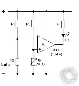
R2 is the bulb and R1 the low value (aka power) resistor (which may need to be bigger than 1/2W for some values & bulbs).
The tested bulb(s) R2 vary from approx 20 Ohm (7W taillight) to 3 Ohm (2x 23W stop) or 1.5 Ohm (4x stop).
The voltage at the power-resistor/bulb junction (R1-R2 & "-" input) has to match the the voltage at the R3-R4 junction (+ input) for the comparator to be at its switching point.
Hence adjust R4 so the LED just turns off with the bulbs as normal (engine off is fine - no voltage regulation is involved hence circuit remains "balanced").
The biggest voltage drop across the bulb's power resistor R1 is when all bulbs are operating. (ie, V=IR so V is max when current I is max, ie, the most bulbs.)
Whilst R1's voltage drop exceeds that of R3, the inverting or "-" input voltage is LOWER than the non-inverting or "+" input, and hence the comparator (output) is off (ie, floating).
If a bulb blows, the current should be lower (or nil) thru R1 so that - subtracted from the +12V rail - means that the "-" voltage rises and should be above the "+" input, hence the comparator turns on - ie, the output connects to 0V/GND and can sink 16mA, hence R-LED RL should be ~12V/0.017A = 706 Ohms => 820 Ohms (1/2W though 1/4W may be ok).
IE - the comparator turns on a LED connected through an 820 Ohm (1/2W) resistor to +12V. The 820R limits the (LED) current to under 16mA to protect the LM339 output.
BTW - I chose 10k for the R4 trimpot as it's a common size; not too much current but enough to generally swamp car noise.
I also chose the voltage drop across R1 & R3 to be 0.5V, though a mere 0.05V should also work - but I'm unsure of comparator behavior with near +V inputs - it should IMO be ok; but most comparators compare voltages closer to 0V/GND.
One problem with a regulated supply is that the Comparator and R3 & R4 have constant voltage but the bulb input does not since it is powered from the vehicle's +12V and hence can vary from (say) 12V to 14.5V, or 20%.
That shouldn't be a problem for single & dual bulbs, but may be a problem for 4 bulbs depending on trimpot sensitivity. (Sensing 4 bulbs means sensing a 25% change (1 of 4), but the signal varies 20%, hence only a 5% adjustment tolerance".
If you include cranking - hence 9V to 14.5V or 45%. So sensing 2 bulbs (50%) is possible...)
The unregulated circuit doesn't have that issue - as the vehicle voltage varies, so do the "reference" points (ie, BOTH the + & - input voltages react similarly to voltage changes so it shouldn't false-switch).
I'd forgotten that Op-Amps and Comparators handle up to 35V supplies and hence can be used in "raw" +12V car environments (excluding spike protection (zenor & resistor, & run LED/load from raw +12V.) Good-bye evil voltage regulators and voltage restrictions.
Posted By: urhottboy85
Date Posted: January 03, 2012 at 12:27 AM
Ok so what's the diagram on the first page? I ashtray have that one built and now I have to redo the whole thing? I'm going off of 5v not 12 anymore
Posted By: oldspark
Date Posted: January 03, 2012 at 12:54 AM
oldspark wrote:
That's just an example using a "high spec" comparator...
And later I refer to the circuit type above... " ...see the "Comparator Operation" section a few screens down...", and the LM339. And " Maybe the type of circuit shown under Bristolwatch/Paisley's "Voltage Window Detector Circuit" ... is what you want?".
But I thought I had posted "that" diagram. It wasn't until Dec30 I realized I hadn't - I did sometime after Nov30, but it either got removed with the spam posted before, else it got lost en-route (it happens; but rarely!).
And I thought that was the 4-resistor circuit you were constructing, and you got a quad comparator hence NOT constructing the sample LT1637 circuit (cannot substitute random components).
|