basic l.e.d. wiring
Printed From: the12volt.comForum Name: Lights, Neon, LEDs, HIDs
Forum Discription: Under Car Lighting, Strobe Lights, Fog Lights, Headlights, HIDs, DRL, Tail Lights, Brake Lights, Dashboard Lights, WigWag, etc.
URL: https://www.the12volt.com/installbay/forum_posts.asp?tid=131827
Printed Date: May 13, 2026 at 11:13 PM
Topic: basic l.e.d. wiring
Posted By: corrollaman
Subject: basic l.e.d. wiring
Date Posted: July 15, 2012 at 3:38 PM
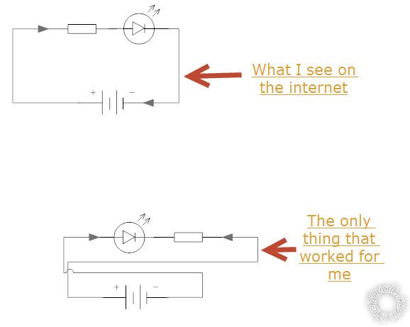
I know I read that you solder negative to positive when doing an array, but this is backwards to what I am seeing on the internet.
Thought I would throw this by the experts for a sanity check. What worked for me also has the correct voltage. I have a power supply with 12V output and when I measure the L.E.D power it is at 2V.
Is what I am doing correct. Everything I show makes me think I am just not seeing it correctly .... SANITY CHECK PLEASE!!! Thanks guys/gals
-------------
AJM
Replies:
Posted By: oldspark
Date Posted: July 15, 2012 at 7:42 PM
How do you know you have the line-end towards +ve?
And where the resistor sits is no issue. It merely has to be anywhere in series with the LED.
Posted By: corrollaman
Date Posted: July 17, 2012 at 7:45 AM
Backward-biased diode.
I thought I was just loosing it, as I stated before.. but I looked over the LED several times.. Negative being the flat side of the LED, Negative being the larger part of the LED... etc..
I then ran across an article that described my setup. https://download.micron.com/pdf/education/lessonplans/electronic_components.pdf
Out of all the youtube videos, and articles I have read trying to understand my predicament, this is the only thing I could find that would explain what I was running into. This then lead me to transistors... Which raised more questions..
So, what would you say about that? (Not being argumentative, just trying to understand 100%) I go big or not at all.. so if i can't understand something.. ie.. this project.. I wont finish it..
-------------
AJM
Posted By: oldspark
Date Posted: July 17, 2012 at 10:12 AM
That's a good reference link.
My condolences - you may be headed down the path of electronics. (Welcome! But commiserations. But then lots of enjoyment.)
And I'd have to check, but the "big element" looking thru the LED being -ve sounds correct. (I can never remember the flat side nor short-lead or square-lead convention.)
But the LED should not work if it is reverse biased.
Having said that, I will not rule out incorrectly marked components.
Though I doubt the "big" being -ve would be incorrect (it's such an automated and exact construction process), I won't discount it.
The most likely is wiring confusion followed by incorrect supply polarity. (I have had the pleasure of seeing a car battery whose case-embossed + & - legend was wrong! So too the terminal sizes since -ve & +ve leads/terminals hooked up normally to the "incorrect" polarities!)
Alas I'm about to hit the sack & am too tired.
I'll get back to you later (kick me if I forget) and take on your "argumentative" stance. (That's a joke. You are not being argumentative. You are reporting your observations. I expect it to be some simple "D'oh" experience. But I thought the same when my mate reported sparks from his correctly connected battery, but it turned out he had the one in a thousand or million situation of an incorrectly labelled mass produced common car battery. And I'd love to see a "reverse constructed" LED!)
BTW - if you do find a d'oh and great embarrassment, please report ASAP. (I've been there, done that.) Until then, IMO you are right until proven wrong. But we'll do a few checks... later.
Posted By: corrollaman
Date Posted: July 17, 2012 at 6:57 PM
I was pretty tired when it was all said and done.. I am traveling right now so I am just researching and doing a lot of reading to prepare for exactly how i want this project to go, how complicated to make it.. or not make it.. and understand it completely so I can do it again or tell a few friends how i made it happen.
I will remind you this weekend when I am actually hands on again and then i can take pics and post them of how backwards it is.. or isnt.. Thanks for the help.. Electronics are awesome.. Never really had a reason to play with all this stuff, but my corrolla project got me started and the passions flowing..
-------------
AJM
Posted By: corrollaman
Date Posted: July 21, 2012 at 1:34 PM
Okay.. made it back in one piece...
Okay.. LED's are essentially Diodes(one way check valves).. So how can you connect them in a Series... positive to negative, negative to positive.. Electricity only flows in one direction through diodes(leds)..
So I hooked up 8 LEDs in what I believe to be parrallel.. .negative to negative, pos to pos.. with a resistor in the circuit..
I dont know how all these people on the internet are able to wire them in a series.. im thinking they are meaning a series to be in a row.. but not the technical aspect of the leads going pos to neg.. neg to pos.. I have included some pics..
-------------
AJM
Posted By: oldspark
Date Posted: July 21, 2012 at 7:45 PM
But first I'd like to repeat "welcome to electronics" (and maybe stress my aforementioned condolences {LOL}), AND add that I was impressed by your work above - including that "101" link.
In fact, no, maybe I won't tell you. You were tired, and then away. That's a rude interruption to your thinking processes yadda yadda... (That's right isn't it?)
Two ways I can tackle it...
The first is coupled with a diode & LED circuit and wiring trick.
The diode symbol is a line and arrow like --->|---
So what?
Well, that symbol has it all...
The arrow points in the direction of the current flow.
[ +ve to -ve, ie (+) +ve ---->|--- -ve (-) so current here flows left to right thru the diode. ]
The other main thing is that it's (vertical or perpendicular) line is the BAND on the diode body, hence the diode's "band" end points to the more -ve voltage if you want it to conduct. (They can be mounted "back to front" for voltage limiting or spike suppression. Forget that for now, but later maybe look at the spike suppression diode placed across relay coils (86 & 85). I/we might discuss that later.)
A trivial thing from the diode "arrow & band" symbol is that ruddy Anode (+ve) and Cathode (-ve) jargon. (I couldn't even remember which meant +ve (anode) or -ve until, perhaps(!?), recently.)
The lile end is a "K" - ie, ---|<--- = ---K--- to that's the Kathode = Cathode end.
Ergo, the other end is the anode, but that's confirmed by the arrow head > which is a sideways A.
Well that's how I remember it. And that's how I could tell people that the anode is the +ve end - ie, working backwards, I knew current traveled +ve to -ve thru the diode hence into the arrow and out of the line/band, +ve so into the arrow = A hence +ve is the anode.
A pause or digression here. Part way thru the above text I thought here I go again - a long reply for a potential one line (7 word) simple answer. And that was before the last block about how I determine +ve = Anode!
But I'm in my typical "101"
Okay, so applying the above to LEDs.
As you said, LED is merely a diode, but it emits light. Hence the LED symbol is a diode with a couple of squiggle-arrows off it to symbolise the emission of photons/light.
[ FYI - voltage-drop = "forward voltage drop" ramble:... IE - optional; skip this for later...
Of course diodes have a forward voltage drop and that drop depends on the type of diode or color of LED, as well as the amount of current thru it.
Common silicon diodes typically have a 0.6 - 0.7V forward voltage drop whilst older germanium types were ~0.2V. New "fast" Schottky diodes are ~0.3V. (As to the current effect, a high-current silicon diode's voltage drop may be 0.6V at low current, and over 1.0V at high current (eg, 100A).)
LEDs vary from typical reds with ~1.7V to whites with ~3.4V.
BTW - the reverse blocking voltage should be infinity - ie, NOT let "reverse" current thru no matter what the voltage is - but in practice there is a "reverse breakdown voltage" which does simple means the reverse voltage at which the diode will break down (ie, conduct, or self-destruct, etc). LEDs may have low reverse breakdown voltages (hence they may need a normal diode in series for AC power etc), but silicon diodes are usually 50V upwards. For 12V automotive systems 50V diodes (eg, 1N4001) should be fine, but usually the more common 1N4004 with 400V PIV (Peak Inverse Voltage) is used. The 1N4 series has a 1A rating (max forward current) and the last digits designate their PIV (but with no direct numerical relationship other than increasing, eg, 1N4001, 1N4002, 1N4004, 1N4007 have 50V, 100V, 400V & 1,000V max reverse voltages (PIVs) respectively. The missing numbers are other voltages that are no longer produced, but essentially the 1N4004 (400V) & 1N4007 (1kV) are the only two still in common production and supply. The 400V 1N4004 rating is better suited to automotive 12V systems anyway since a vehicle can have high-voltage spikes of 200V etc.
/end vd ramble ]
Anyhow, back to your problem of LEDs in series.
Draw a few diode symbols in series.
Now think how could you connect them so that they all pass current in the same direction? IE - which way do the arrows point? Then compare that to what you wrote in the first line of your last reply...
Kicking yourself yet?
You had the answer - a diode "the wrong way around" blocks the current. (Or as I say, it hits a brick wall - ie, the line or band.)
[ More optional ramble
Incidentally (again!), you may know that the current thru all series components is the same (it has to be - where else can the current go?). And (therefore or hence...) the sum (total) of all the voltages across each component adds up to equal the supply voltage.
Hence your resistor should still carry (say) 20mA but at a lower voltage when there is more than one LED in series (not parallel!!).
That means a lower resistor, but the single LED's resistor should still work fine. (LED dimness is NOT proportional to the resistance. But that's another topic. Put is this way, LEDs are NOT amongst the first things to be taught in electronics though they may be covered early on because they are great to use in circuits, but few understand LED characteristics. In fact I still have colorful discussions regarding LEDs - usually along the lines of how critical there AREN'T wrt to voltage, and to an extent, current.
/end ramble ]
Maybe I should have started with the second way I could tackle your problem, but it might be a spoiler if you haven't kicked yourself yet...
Think about how other "polar" devices are connected, eg:...
How do you align batteries in torches and remotes etc?
How do series magnets align themselves?
BTW - I haven't gotten further on your possible "faulty" LED. I've bee meaning to search for instances of backward constructed LEDs - like the car battery I mentioned with incorrectly molded + & - terminal labels.
Though maybe the LED's flat side could be misaligned (IMO still doubtful though), I consider it almost impossible to invert the internal connections to the electrodes (terminals/wires) - ie, the Kathode/-ve should always be to the bigger "flag" electrode (as usually seen looking thru the LED from the side).
Isn't it nice starting off a Sunday with a nice relaxing read?
Till next.... (Sunday?)
Good luck.
Posted By: corrollaman
Date Posted: July 22, 2012 at 10:14 PM
Recreational powders... what is that.. hehe I have no idea what your talking about.. <G>
Yes, I was totally kicking myself. I was sooooo relieved to know I was just understanding it wrong.. I guess I had just assumed I knew enough..
Thank You so much for the explanation... I knew enough to be confused... lol.. the Radioshack guy directed me toward the internet and that didnt answer my question... so he pulled the busy card and would call me back.. lol.. This is of course after I went in with my breadboard all wired up and he took pictures.. hehe
Now that I know what im dealing with and have successfully setup the series/parallel up .. So next is figuring out how to calculate the resistors. 2 resistors.. one for the running tail light and one for the brake.. figuring out the best contrast without blinding the people behind me.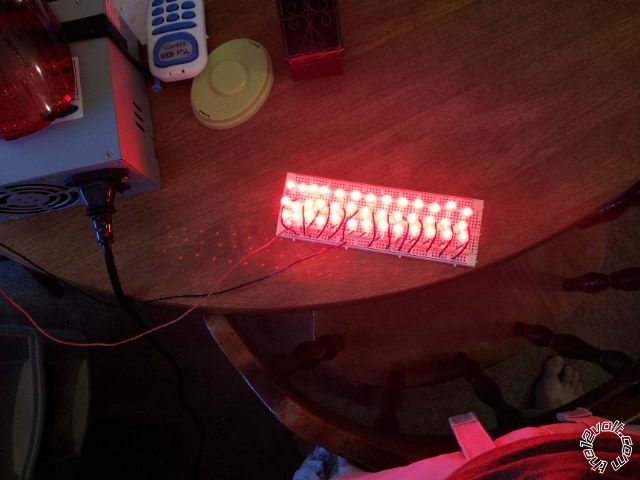
I will start a new thread for that.
Thanks again
-------------
AJM
Posted By: oldspark
Date Posted: July 22, 2012 at 11:25 PM
"I knew enough to be confused... lol." Oh yeah - I know that one!
With the resistor calcs, the first to get is the one for max brightness (brakes).
You then ADD another series resistor to get the required taillight dimness.
The final circuit is with (say) the added dim resistor from +12V to the "max brightness" resistor to the LED+ (with LED- to GND).
An SPST relay is then connected with 30 to +12V and 87 to the junction of the 2 resistors with the relay coil actuated by the brake switch (eg, 86 from the switched +12V and 85 to GND).
When the brake is applied, the relay bypasses (or shorts out) the "dim" resistor leaving only the "bright" resistor in series, hence full brightness.
There are other methods too.
And if you have parallel strings, you'll have to decide if a single dim and single bright resistor is acceptable.
Ideally each string should have its own resistors, but that makes the dim bypassing difficult though each string could have its own "bright" resistor and a single dim resistor to feed the lot. That way, if strings fail, the rest can be no brighter than "bright" and they won't blow.
If that's not understood, consider a few LED strings supplied through a single resistor. That resistor might limit the LED currents to 20mA. But if one string is lost, it means more than 20mA to the remainder. Etc etc.
Single resistors for multiple strings are often used where there are MANY strings eg, 10 or more so that loss of one string increases current by only ~10%, 2 strings ~20% etc.
If only a few strings - say 2 or 4 - then one string loss can mean a doubling or extra ~30% for the remaining strings, and that could be enough to severely effect LED life.
Mind you, the above are subjective and determined by string or LED loss probability (ie, statistics). LEDs are supposed to last forever in theory, but then there is the wiring, fatigue etc.
Usually multiple strings are PWMd (Pulse Width Modulated) whereby the Duty Cycle of the PWM determines the brightness. That can be done with a single "bright" resistor for each string (to protect the string) and then the PWM is set for (say) 30% for taillights and switched to 100% (or 99% etc) for bright.
Resistors can even be omitted when the PWM is instead set for (say) 20% (dim) and a max of 80% (bright) assuming 80% is the max duty cycle tolerated by the LEDs without any current limiting series resistor.
PWM also has the advantage that brightness can be altered without the need to change resistors.
PWM is another topic. I'll put that under "Avalanche Theory" as in one electronic issue avalanches into a plethora of other
Posted By: corrollaman
Date Posted: July 23, 2012 at 2:35 PM
-------------
AJM
Posted By: corrollaman
Date Posted: July 23, 2012 at 2:40 PM
-------------
AJM
Posted By: corrollaman
Date Posted: July 23, 2012 at 3:08 PM
This is a shot from the example I am using as a reference.
He doesnt show a relay.. but obviously he is using something outside of what the schematic is he put together.....???
-------------
AJM
Posted By: corrollaman
Date Posted: July 23, 2012 at 3:22 PM
-------------
AJM
Posted By: KPierson
Date Posted: July 23, 2012 at 3:32 PM
-------------
Kevin Pierson
Posted By: oldspark
Date Posted: July 23, 2012 at 8:24 PM
oldspark wrote:Yeah - I don't know why I wrote that. I'll put it down to being early morning, pre-coffee & pre-shower. (You need to develop reasonable excuses when dealing with electronics. Take the rap, but with dignity. IOW, your excuses will have to be better than mine.)
Ideally each string should have its own resistors, but that makes the dim bypassing difficult...
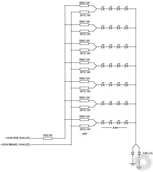
Apart from the parallel resistor topology of the circuit you posted, it's been done by an amateur. I pick that from the resistor values that do not have to be that specific (preferred values should always be acceptable - eg, 270R & 820R in that case; where R means Ohms).
Also those diodes should be unnecessary in a 12V application. (If the LEDs can handle their forward voltage, then they shouldn't need ordinary diodes as they might for AC solutions.)
And I don't know why the single big resistor in the dim supply. Maybe it's to allow easy variance of the dim level? (But then ensure the dims are bight enough, and add that resistor later if needed.)
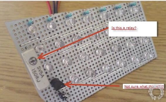
And yes, the big white thing is a resistor, 150 Ohms (150R) of probably 5W rating (5A??).
I have no idea what the black thing is. Limped resistors maybe (which is bad), or a tap/connector, some type of fuse, surely not a thermal sensor?. It's small to be a voltage regulator that powers the LEDs. It might be a transistor for extra control...
I'd suggest my series method of connecting the resistors instead of its parallel method, though that depends on your flashing brake lights.
Do you want your brakes to flash between bight and dim(tail), or bright and off (dark)?
Also, the flashing may suggest a PICAXE. That's easier than the adding the timing circuits required.
Assuming such flashing is not illegal, it can be speed related (less flashes at low speed) and it is usually limited to no more than 3 flashes.
A PICAXE can do all the dimming required (using PWM) as well as be programmed with the relevant flash code - and even feed with a speed signal.
The PICAXE would have 2 or 3 inputs - tail, brake and optional speed. One output to a MOSFET ($3) that connects all LED strings to GND and is then PWMd or modulated for dim and flashing. No relays, and each string need only have the one "bright" resistor (all connected to +12V or IGN +12V etc).
As an example of how simple(?) it can be, see mp3car's Controlling back lights directly?.
That is similar to your project and goes through various suggestions before the OP decided on the PIC solution (see page 3).
POST EDIT: I just checked that mp3car thread and it does not have the last replies that I expected. Maybe the OP deleted the relevant replies & coding else I picked the wrong thread.
Posted By: corrollaman
Date Posted: July 23, 2012 at 10:08 PM
If you look at this link, https://petemills.blogspot.ca/2012/04/tenty-led-brake-lights.html, I would like a pulse of brake light that is similar to Peters. I believe it's legal to do up to three pulses without being classified as a flasher, which is illegal in the states.(and not someone in a trench coat, kind of flasher)
I'm on board with the PICAXE idea.. being green behind the ears, but enjoying the hell out of learning about electronics makes that suggestion an easy Yes. I read through Peters entire guide/setup and when i did further research i was going to have to buy a software application and some kind of PIC programmer etc.. (wasn't too keen on the idea of spending even more money)
I gather from what you describe it wouldn't take much to get the PICAXE, the software is free, and from what I read on that Ch. 3 all i need is a serial cable, which i have some at the office. I wasn't sure what a MOSFET was.. but after I googled it.. its a transistor.. so now all I need to do is figure out how all this comes together. More research.. :-D
So far I am already on board with doing 48 LED's in a an array of 3 per string.(based off of a LED array calculator)
I have checked the voltage from where I am getting power and it sits around 13.2-14.4 depending on if i am really giving it the gas.. I am wondering if I should put a voltage regulator on it or not.. and what voltage would i use for my calculations. I am thinking when this is all put together I may have to adjust my Resistance a few times so as not to blind the people behind me.. hehe I have also wondered about using a capacitor and a voltage regulator.. keeping in mind that I want this perfect so I don't destroy the leds and they outlast me.
Okay I am done rambling on and on....
Once I have enough information, and sleep. hehe I will put together a drawing of all this.... my dreams have been full of leds.. hehe
(LEDS: Red 8mm .5 watt 3.4-3.6V, 20mA Vf, 100Kmcd)
-------------
AJM
Posted By: oldspark
Date Posted: July 23, 2012 at 11:59 PM
Nah - pick any axe when needed. (ha ha)
And the ATmega stuff is good too (ie, Arduino).
Not that I'm that familiar with ATtiny requirements, but the PICAXE only requires a 5V regulated supply, and 2 resistors that are required for programming. They have very low power consumption, hence small 100mA V-Regs are usually fine. (Good too for power conservative projects - solar & battery etc.)
You then add whatever other components are needed, like automotive voltage protection (for the VReg = eg, reverse spike diodes, MOV or +ve spike limiters assuming 100V etc spikes), I/O (input/output) connectors and their filter or buffer circuits - eg, RC filter for inputs; resistor and MOSFET for outputs.
The MOSFET is like a transistor but is controlled by voltage instead of current. (Transistors have a gain - aka β or Beta - which is the (max) ratio of output-current :to: Base (input) current.)
A FET only takes nA (nano-Amps) thru its Gate (equivalent to a transistor's Base) instead of the several mA etc by a transistor Base.
A FET requires typically ~4V-5V above its Source (equiv to transistor's Emitter) to turn it fully on. (+ve for N-channel, P-chanel requires 4-5V BELOW the Source voltage).
A FET's (MOSFET's) output is usually quoted as resistance, ie, RDSon (Resistance of Drain to Source when (fully) ON).
MOSFETs typically have well under 1R (1Ω) on resistance and often measured in mR (mΩ).
It's easiest using an N-channel MOSFET where its Gate needs to be (say) +5V higher than the Source to turn it on.
That's great because you'll probably want to use GND switching. (Many "control circuits use GND switching - eg, car alarms, immobilisers, computers, ignition coils, injectors. It's also known as "Open Collector Output" which means that it is grounded when on, and "floating" when off. I've written about that on the12volt as well as elsewhere, but there are lots of other references.)
The reason for GND or Open-Collector switching is that it doesn't mater what voltage the switched component is.
EG - your 5V uPC (PIC, AT, whatever) can't supply (say) +12V without difficulty, so instead have it turn on a switch that grounds the target device (LEDs).
It does assume that you can isolate the LEDs from GND - ie, normal bulbs are often grounded thru their holder and the chassis/body. But I suspect that is not an issue in your case.
I wonder about your red LED voltage of ~3.6V, but I'll check up on that. Reds are usually ~2V but maybe these high output (and high Wattage - 0.5W) LEDs are different. Maybe they are whites with a red lens?
Normally I'd suggest 4 maybe 5 series red LEDs for 12V automotive systems, whereas it's usually only ~3 for whites (ie, ~3.5V each).
That's allowing for voltage dips below the usually battery voltage of ~12.6V (maybe down to 12V or 11V when idling with headlights on etc).
Of course it must also handle the normal long-term system voltage of 14.2V to (max) 14.4V, and maybe the odd 14.5-15V or 16V (after cranking etc). But that's where LED characteristics often tolerate such "over-voltages" - ie, if designed for your norm of (say) 14.2V but has short duration over-voltages of 15V - 16V (ie, up to 30 seconds?).
For 3.6V LEDs, I'd use no more than 3 in series, hence 3x3.6 = 10.8V which provides enough margin for the resistor drop and any MOSFET drop.
Assuming 14.4V, that means 14.4-10.8V = 3.6V across the resistor. (Hence I might use 4 series LEDs, but many seem to prefer a resistor...)
Hence from V=IR (Ohm's Law), R = V/I = 3.6V/20ma = 180R. (Wow - bang on a preferred value. The other nearest are 220R & 150R. I might be tempted to use 150R is the FET adds a reasonable voltage drop...)
It's wattage: 3.6V x 0.2A = 0.072W, hence a 1/8W (0.125W) or 1/4W etc. Traditionally I'd use a 1/2W resistor as these use to be physically more robust, but last time I bought, 1/2W resistors were the same size as the old 1/4W resistors. Get whichever is cheapest or common and suits your design.
(Or Wattage using a combined V=IR & P=VI formula, namely P=VV/R = IIR => 3.6 x 3.6 / 180 = 0.072W or .02A x .02A x 180 = 0.072W. See - it all agrees, otherwise I've made an error somewhere...)
Hence n-number of strings comprising 3 LEDs and a 180R resistor per string.
Total max current is 20mA times the number of strings (ie, n x 20mA or n x 0.02A).
The add the required dim resistor per string, OR sove a MOSFET between the -ve ends and 0v (GND) and have a uPC PWM for dim tails, fully on for brake, and modulating (flashing) for flashing stops.
That modulation could be between fully on (brakes) and PWM'd tails, or fully on and off.
Tails too dim or bright? Change the programmed PWM value.
Want to increase flash rate with speed? Program the speed sensor adjust the flash frequency.
Want to change the number of flashes or even the on-off ratio (duty cycle) - maybe with varying speed? You guessed it, just change the program.
Yes, these uPCs have a bit of an initial learning curve, but then almost anything can be done without the need to add or change resistors, capacitors, etc.
BTW - look at the PICAXE 08 series (8 pin), often designated by a PIC12Fxxx number depending on model.
The later 08M is quite good but the latest 08M2 has more improvements. Both have enough program space and features for what you want.
Incidentally, I'm looking at getting preferably the SMD (surface mount) AXE230 kit, though DIL [Dual In-Line (pins - ie, chips with leads/pins)] like the RKP08 (RKP08c) are also available.
Google the above numbers... Unfortunately some of the kit descriptions are vague - ie, does the AXE230 come with the 08M or 08M2 already soldered in place?
Probably the DIL version is best for testing etc. Production may call for the much smaller SMD version. (Isn't it ridiculous when the 2 programming resistors are as large as the entire PIC08 with it's thousands of transistors etc?)
Just another short reply...
PS - to clarify if not already read or implicit, a voltage regulator should not be necessary for the LEDs. (But the uPC. PIC, AT, whatever, will need its voltage regulator.)
Though many seem to use voltage regulators or current limiting devices (a single limiter for several strings - if one string fails, what's the point??!) and write how successfully they have operated, I have yet to see any of them say how they operate whereas non-regulated circuits didn't. IE - they are usually those that think LEDs have exacting voltage or current criterion, hence they travel down the complicated and more expensive overkill path.
Look at OEM vehicle LED lighting. Nothing more than a resistor in series with LEDs. No other form of current (or voltage) regulation. Yet they seem to last ages. (Tell me if I'm wrong.) My only failure was a broken wire within an after-market LED stop/tail "bulb".
Posted By: corrollaman
Date Posted: July 24, 2012 at 8:22 AM
Awesome. Thank You soooo much.. I am sure I will have more questions, but it is going to take me a while to digest all this in between my 1 yr. old and my travel. Once I get everything together I need I will end up putting together the schematics and passing them on to you.
Again, much Thanks!!
-------------
AJM
Posted By: corrollaman
Date Posted: July 24, 2012 at 10:49 AM
"The reason for GND or Open-Collector switching is that it doesn't mater what voltage the switched component is.
EG - your 5V uPC (PIC, AT, whatever) can't supply (say) +12V without difficulty, so instead have it turn on a switch that grounds the target device (LEDs).
It does assume that you can isolate the LEDs from GND - ie, normal bulbs are often grounded thru their holder and the chassis/body. But I suspect that is not an issue in your case. "
I will be wiring this directly to a bulb which is grounded.(will have 3 wires coming out of it) This way I dont have to get into any of the wiring harness.
"Assuming 14.4V, that means 14.4-10.8V = 3.6V across the resistor. (Hence I might use 4 series LEDs, but many seem to prefer a resistor...)"
-As for the led's in a series without a resistor... if you were doing this project would you go without the resistor and just do 4 in a series? I wonder what the pro's and con's are of using or not using the resistor?
"I wonder about your red LED voltage of ~3.6V, but I'll check up on that. Reds are usually ~2V but maybe these high output (and high Wattage - 0.5W) LEDs are different. Maybe they are whites with a red lens?"
-->LEDs i bought(https://www./itm/200762934769?ru=http%3A%2F%2Fwww.%2Fsch%2Fi.html%3F_sacat%3D0%26_nkw%3D200762934769%26_rdc%3D1)
I cant think of anything else..
-------------
AJM
Posted By: oldspark
Date Posted: July 25, 2012 at 3:29 AM
Reds should always be ~2V. It's the chemicals involved that determine the color, and the elements/chemicals determine the voltage. That's how I recall it anyhow.
They claim it's a clear lens. Maybe the lens is clear but there's a filter underneath? Or maybe there are 3.6V reds. I doubt that they'd use 2 reds in series.
Incidentally, I looked at wiki's LED_circuit page (which is to be deleted and replaced by its Light-emitting_diode page), and John Hewes's Electronics Club led page.
They confirm the bigger electrode is the -ve (Cathode), and I now have a new rule - the flat side if the LED-base is a flat line, ie, a -ve, and ergo that's the -ve end. (But I always look thru the LED to check.)
They have nothing about reds being >3V.
But I like how John Hewes's led page has a section "Avoid connecting LEDs in parallel!". I'll quote that next time someone argues - especially about using a single current limiter for multiple LED strings.
If I did this project would I go without the resistor and just use 4 in a series? (Assuming white etc or up to ~3.6V each.)
Probably yes.
But that's a combination of factors, eg:
- I know some that do the same and have not complained - eg, 6 to 8 reds, or 4 whites, etc. (I believe some on the12volt have.)
- I'm prepared to lose a few in my error(?) and then retrofit a resistor i place of one of the LEDs, or rewire appropriately.
BUT, if I am using PWM to modulate the brightness, I'd merely reduce the maximum duty cycle - ie, from 100% to 90% or 80% etc.
Note that the LED is a current device. It is over-current that kills them, not over-voltage. (And it is current that controls them - eg, their brightness - they are not "linear" devices like bulbs where current is (closely) proportional to voltage, ie, V=IR.)
What I am saying is that the voltage is essentially irrelevant for a LED. The voltage is merely selected to provide the appropriate current for it.
But in that, it must be understood that there is a relationship between V & I (it's a donkey & cart or chicken & egg thing) and that the voltage cannot be so high as to puncture the LED - ie, semi-conductor breakdown - by exceeding PIV or Vf-max limits, ie Peak Inverse (reverse) Voltage or max Forward Voltage.
[ I think that's why 110-230VAC LED lights break down so much. They seem to use mere diode rectification with highish light output. That means highish RMS (ie, "average") current/voltage, but the peak voltage will be ~1.4 times the RMS voltage, hence I suspect premature failure. I don't know why they don't use an SMPS circuit (or full-bridge rectification and filtering though the caps are an issue) and convert the AC to a steady DC. Mind you, it could also be the long series strings involved - lose one and lose them all (immediately if open-circuit; eventually if short-circuit failures), but then use an SMPS to convert to lower voltage parallel strings. ]
Ooops - did I digress yet again?
Anyhow, I assume you have a DMM (multimeter).
Test with whatever voltage and resistor and measure the current.
Ideally a 2nd DMM/voltmeter to measure the LED voltages, though using a single DMM should be ok (the current measurement inserts a resistance, but that should be negligible, and voltage readings will not effect the circuit).
Besides, knowing the resistance and its current, you can calculate its voltage drop accurately (V=IR) and hence calculate the voltage across the LED(s) - ie, Vs - Vr (Supply voltage minus Resistor voltage).
An initial test with series LEDs should be to see how similar their voltages are. They will vary a bit... (Even LEDs manufactured o the same silicon die vary in their voltage for a given current - unless they have solved that issue in a past few years.)
You might even want to burn a few to see what current blows them almost immediately. (Note that you must watch the DMM current reading just before failure. It will drop to zero as soon as they/it blows - unless it blows in short-circuit mode which is unlikely (for over-current) but that short-cct measurement is useless anyway.)
That might give you a bit of confidence that they can tolerate some extremes.
But be aware that stressing may not lead to immediate failure - it may just decrease their lifespan. Also many components fail on over-current for thermal reasons and they may take a while to warm up (thermal inertia), though LEDs generally have little thermal inertia and blow quickly.
Make sure you have the right topology before you construct the final. Having to rewire a (say) 24-LED light from 6 strings of 4 to 8 strings of 3 is a PITA!
Changing of resistors or adding a PWM won't be as painful.
Remember too that the LEDs have to be bright enough with the car's lowest voltage. However you should find that dropping from 14.4V to (say) 11V or 9V does not have a major effect. IE - the voltage might drop ~35% to 9V but the LED intensity might only drop 10% - 20% etc.
Posted By: corrollaman
Date Posted: July 25, 2012 at 4:45 PM
Could you possibly do a mock up of the connections.. This is as far as i have gone..
Remember your talking to someone who is ... what is the term.. still ignorant.. but learning..
-------------
AJM
Posted By: corrollaman
Date Posted: July 25, 2012 at 10:24 PM
okay.. let me repost.. too bad i cant delete the last one..
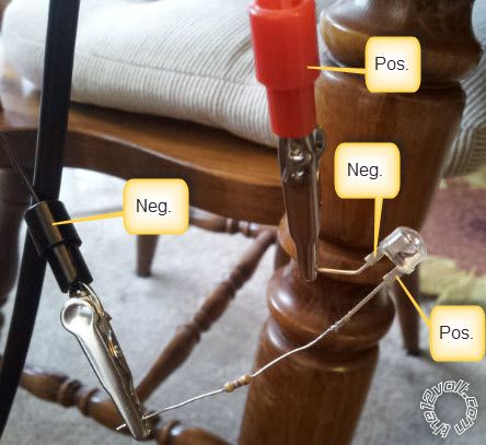
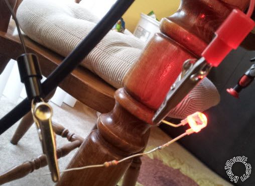
I figured I had just missed something, which i think i did, but I re-read everything you posted and all the information was there except for what I am posting now. See pic below:
So this is where I am at.. Had I taken the time to read your post earlier.. or had the option to delete the last picture.... I would have.
-------------
AJM
Posted By: oldspark
Date Posted: July 26, 2012 at 3:58 AM
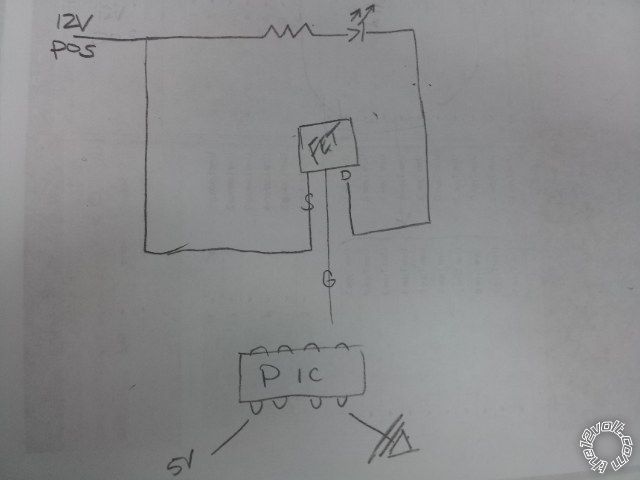
The (MOS)FET should be in series with the LEDs. And (I think...) its D & S swapped (S to GND, Drain to the -ve end of the LEDs or their negative-end resistor).
And maybe include an ~1M to 10M resistor from the MOSFET's Gate to Source (GND) to ensure it is turned off if open-circuit (eg, when the PIC's signal for the MOSFET's Gate in "not on" (ie, an open-collector output as opposed to both pull-Lo and pull-hi to +12V).
Unless you do want it fully on (with bright LEDs) in in case of PIC/circuit failure?
The FET could be omitted initially (and its D & S pins shorted out (joined) with an temporary wire link) so that you get the "straight supply" voltage with no FET D-S voltage drop. You can then confirm max LED brightness and optionally the current.
That then confirms LED operation without involving the FET.
If that's ok, add the FET and confirm its on-off by a wire - maybe with an inline resistor to its Gate (100k?) - being touched to +12V (on) and off (GND).
Probably too ad a resistor between the PIC output and the Gate. Anywhere from (maybe; it depends the PIC's specs) 100R to 1k or 1k (Ohms). Its function is to prevent PIV damage by limiting output current (or inward "sink" current).
[ eg, the 555 timer has a 200mA source/sink limit. Hence a resistor of at least 82 Ohms from its pin3 (output) to anywhere on the circuit (ie, +12V & GND) protects it since I=V/R = 12V/82R = 146mA - well below it's allowed sustainable 200mA. ]
The current to drive a FET Gate is nano-Amps; eg I=V/R = 12V/12nA = 1GigaOhms. Hence 1M should be fine, but it seems many chose a common value 10k or 1k.
[ Better not too high a resistance as weak electrical noise could interfere and cause fast analog switching (instead of our "digital" full-off and full-on (even when "modulated" by the PWM which is "digital" but with varying on times. ]
Then 2 stages.
First the initial basic and "fall back" circuit without the PIC.
Top of LED string (ie "top" = +ve LED end) to +12V.
-ve Kathode end of LED string to the bright resistor (820R? 680R? with its other end to the added dim resistor AND MOSFET Drain else relay contacts (ie 30 or 87).
MOSFET Source or other relay contact (ie 87 or 30) to GND (0V).
The remaining (bottom) end of the added dimming resistor also to GND.
With the FET off or with relay contacts open (ie, the relay is de-energised), the LED current flows thru the LEDs and both the bright and dim resistors and is hence DIM.
The FET-ON or relay closed bypasses the dim resistor to GND, hence current thru LEDs thru the bright resistor then thru FET or contacts to ground, hence the LEDs are bright.
IE - FET or relay turned on for BRIGHT LEDs.
The 2nd & final stage is with the PIC providing bright/dim PWM and flashing control etc.
Relay contacts are replaced with MOSFET (connected as above).
MOSFET Gate (with say a 1M pull down resistor to GND) thru (1k?, 10k?) resistor to PIC PWM control signal output.
Remove the dim resistor. [Pull at least one leg, or cut its wire for later fallback, or use a switch or (maybe - subject to corrosion and vibration) jumper or header pins (yeah - if current rating ok...) if you want easy swapping between PIC & "dumb" version.]
Or you could leave the dim resistor in place, but then the LEDs will not extinguish unless the LED +12V (or GND) is removed. It will PWM etc between fully bright and taillight dim.
Voltage regulator:
Only one is needed to power the PIC itself.
Inputs etc do not need "voltage regulation", but they usually cannot exceed the PIC's 0-5V. But 12V etc inputs can be scaled down using a voltage divider (whose output is proportional to input as the on the ratio of 2 resistor).
For a car there might (should?) be some extra protection, but that can be added later (caps, maybe a resistor & zenor, or MOV (for spike protection).
I'd suggest the common 7805 5V 1A regulator (in a TO-220 3 terminal package) for ~$2. The slightly cheaper and much smaller 100mA 78L05 could be used, but maybe the easier to handle and larger 1A version for the initial prototype.
(An adjustable & thermally self-protecting 317 can be also used by adding 2 resistors, but maybe KIS it now & use the preset 7805 5V regulator._
Both 780x & 317 regulators handle a max ~+35V supply depending on current and heat-sinking.
The final thing is grounding, the PIC should be well grounded to the FET, but the FET to LED assembly;s GND should be separate and heavier, but that's probably thru the GND body/chassis anyway. The 7805/PIC +12V can be on the same circuit as the stop and tail-lights (are your lights or brakes on without IGN? Maybe then power the PIC from +12V, or diode feds from IGN +12V and brake-on +12V and tail +12V, so if any turn on, the PIC (boots up) & operates.
Posted By: corrollaman
Date Posted: July 26, 2012 at 11:57 PM
Good afternoon Oldspark.
I finally figured out why I couldnt read Current.. Long story but took 2 days to realize the issue.. (broken terminal on meter)
Readings for the LEDs:
.021 Amps
~2.027 Volts (I'm not sure where the seller on ebay got ~3.4-3.6V for red.. he also claims 100Kmcd
I just finished wiring up 6 LEDs in a series and they are all sitting at 1.994 V except for one at 2.037V( I dont think I have to worry about a tenth of a Volt)
Currently waiting for all my stuff to come in that I know I need..
I will post an updated schematic tomorrow.
-------------
AJM
Posted By: oldspark
Date Posted: July 27, 2012 at 3:00 AM
That's good too - I was wondering if I was some sort of idiot claiming ~2V when they reckoned ~3.5V.
Your LEDs look well matched. I think 1/20th of a Volt (0.037V) is pretty good.
So that's 6 in series = 12.0V at ~0.2A = 20mA.
Assume 20mA is their rated DC max, so drop 2.5V (14.5V-12.0V) @20mA => R=V/i = 125R => 120 Ohms (preferred value) else 150R.
So 120R for your "bright" resistor with 6 LEDs in series.
You'll have to decide the number of LEDs. All strings should have the same number of LEDs (so that none are different) but that depends if the total number is divisible by n x s, ie the number of LEDs in a String times the number of strings. You might find that 5 or 4 in a string works better...
If bright = 120R I'd assume dim would be around 470R, hence add a 470-120 = 350 => 330R or 390R resistor in series with the 120R.
That assumes my topology where bright & dim resistors are in series and the MOSFET or relay contacts short out (bypass) the dim resistor when brakes are on.
But if you are going to PWM them instead, then just the bright 120R and through the FET which is either fully on for bright, or PWM'd for dim, of off for off.
Note that those resistors are for EACH string of 6 series LEDs.
If you change the number of LEDs, the resistor value(s) needs to be changed.
But the FET (if used) is connected between the common of all strings (ie, join their ends together - one end to +12V, the other to the FET) with is other side (Source) to GND.
Good luck.
Posted By: corrollaman
Date Posted: July 27, 2012 at 11:59 AM
oldspark wrote:
Almost...
The (MOS)FET should be in series with the LEDs. And (I think...) its D & S swapped (S to GND, Drain to the -ve end of the LEDs or their negative-end resistor).
And maybe include an ~1M to 10M resistor from the MOSFET's Gate to Source (GND) to ensure it is turned off if open-circuit (eg, when the PIC's signal for the MOSFET's Gate in "not on" (ie, an open-collector output as opposed to both pull-Lo and pull-hi to +12V).
Unless you do want it fully on (with bright LEDs) in in case of PIC/circuit failure?
The FET could be omitted initially (and its D & S pins shorted out (joined) with an temporary wire link) so that you get the "straight supply" voltage with no FET D-S voltage drop. You can then confirm max LED brightness and optionally the current.
That then confirms LED operation without involving the FET.
If that's ok, add the FET and confirm its on-off by a wire - maybe with an inline resistor to its Gate (100k?) - being touched to +12V (on) and off (GND).
Probably too ad a resistor between the PIC output and the Gate. Anywhere from (maybe; it depends the PIC's specs) 100R to 1k or 1k (Ohms). Its function is to prevent PIV damage by limiting output current (or inward "sink" current).
[ eg, the 555 timer has a 200mA source/sink limit. Hence a resistor of at least 82 Ohms from its pin3 (output) to anywhere on the circuit (ie, +12V & GND) protects it since I=V/R = 12V/82R = 146mA - well below it's allowed sustainable 200mA. ]
The current to drive a FET Gate is nano-Amps; eg I=V/R = 12V/12nA = 1GigaOhms. Hence 1M should be fine, but it seems many chose a common value 10k or 1k.
[ Better not too high a resistance as weak electrical noise could interfere and cause fast analog switching (instead of our "digital" full-off and full-on (even when "modulated" by the PWM which is "digital" but with varying on times. ]
Then 2 stages.
First the initial basic and "fall back" circuit without the PIC.
Top of LED string (ie "top" = +ve LED end) to +12V.
-ve Kathode end of LED string to the bright resistor (820R? 680R? with its other end to the added dim resistor AND MOSFET Drain else relay contacts (ie 30 or 87).
MOSFET Source or other relay contact (ie 87 or 30) to GND (0V).
The remaining (bottom) end of the added dimming resistor also to GND.
With the FET off or with relay contacts open (ie, the relay is de-energised), the LED current flows thru the LEDs and both the bright and dim resistors and is hence DIM.
The FET-ON or relay closed bypasses the dim resistor to GND, hence current thru LEDs thru the bright resistor then thru FET or contacts to ground, hence the LEDs are bright.
IE - FET or relay turned on for BRIGHT LEDs.
The 2nd & final stage is with the PIC providing bright/dim PWM and flashing control etc.
Relay contacts are replaced with MOSFET (connected as above).
MOSFET Gate (with say a 1M pull down resistor to GND) thru (1k?, 10k?) resistor to PIC PWM control signal output.
Remove the dim resistor. [Pull at least one leg, or cut its wire for later fallback, or use a switch or (maybe - subject to corrosion and vibration) jumper or header pins (yeah - if current rating ok...) if you want easy swapping between PIC & "dumb" version.]
Or you could leave the dim resistor in place, but then the LEDs will not extinguish unless the LED +12V (or GND) is removed. It will PWM etc between fully bright and taillight dim.
Voltage regulator:
Only one is needed to power the PIC itself.
Inputs etc do not need "voltage regulation", but they usually cannot exceed the PIC's 0-5V. But 12V etc inputs can be scaled down using a voltage divider (whose output is proportional to input as the on the ratio of 2 resistor).
For a car there might (should?) be some extra protection, but that can be added later (caps, maybe a resistor & zenor, or MOV (for spike protection).
I'd suggest the common 7805 5V 1A regulator (in a TO-220 3 terminal package) for ~$2. The slightly cheaper and much smaller 100mA 78L05 could be used, but maybe the easier to handle and larger 1A version for the initial prototype.
(An adjustable & thermally self-protecting 317 can be also used by adding 2 resistors, but maybe KIS it now & use the preset 7805 5V regulator._
Both 780x & 317 regulators handle a max ~+35V supply depending on current and heat-sinking.
The final thing is grounding, the PIC should be well grounded to the FET, but the FET to LED assembly;s GND should be separate and heavier, but that's probably thru the GND body/chassis anyway. The 7805/PIC +12V can be on the same circuit as the stop and tail-lights (are your lights or brakes on without IGN? Maybe then power the PIC from +12V, or diode feds from IGN +12V and brake-on +12V and tail +12V, so if any turn on, the PIC (boots up) & operates.
Good Morning! These are my changes based on the above.
-------------
AJM
Posted By: oldspark
Date Posted: July 27, 2012 at 9:12 PM
I've redrawn with some changes and notes.
Some changes are merely "layout" - eg, the 1M MOSFET G-S resistor moved to emphasise it's between G & S to ensure the MOSFET remains OFF when no other Gate signal applied.
Also a symbolic splitting of the GNDs since the LED & MOSFET grounds will be "heavy" for LED (or bulb) current while the PIC ground can be "light" (ie, 100mA max) and tied to the inputs.
I also added another sting to confirm how the other strings are connected.
I was also going to add the "stage 1" alternative for the FET - eg, the dim resistor with its paralleled 30 & 87 relay contacts DS FET connections. IE - the resistor and relay can be used as a backup in case the PIC fails (with some re-wiring, and then it's ONE dim resistor for ALL strings which means a smaller value ("dim-Ohms" divided by the number of strings) with a higher wattage.
But there are different ways of doing that - eg, multiple "paralell" dim resistor as per that other link's circuit, or one big resistor as per my "series" circuit knowing that then "dim" will a bit brighter if any strings fail...
Since this is stop & tail, only one output & FET circuit is needed.
If it included left/right flashers, then a 2nd output and duplicated FET circuit would be needed.
You next theoretical step is to determine how the stops & tails are powered. IE - are they both via IGN, or both anytime, or tail anytime and stop only with IGN? Hence what +12V circuit supplies the light & brake switches that illuminate the lights?
That will decide where you get your PIC power from, unless you want to change the standard wiring (eg, maybe brakes on anytime whereas they were originally only on with IGN.
The other part is confirming that both tail & brakes are +12V switched, but that is the most common method. (Lights are almost always permanently grounded and +12V is switched to them to turn them on. However, especially with the advent of electronic management systems, it may be that their input circuits (switches) are ground signals and the electronics convert that to +12V (maybe via a relay).
But we can discuss the possibilities or best way once their power sources and switching are confirmed.
Then comes the "input" decisions.
Since your stops & tails can be on independent of each other, you need to sense BOTH - ie, 2 inputs.
But that doesn't mean using 2 PIC inputs. You can combine the 2 signals (through resistors) to get an analog output. EG - both off is 0V. Tail is 2V. Stop is 3V. Both means 4V etc.
A single PIC analog input can then used to determine what is on.
The latter is not an issue for you whereas with flashers included, it's another 2 inputs (left and right or both), hence another 2 PIC inputs or another one PIC input if we use a similar brake/tail combination trick.
Of course, tails, stops, left & right flashers could be combined into a single PIC input, but that starts to get nightmarish! (Only in desperate situations might we do that - eg, if we are one input short).
[ As you probably already see, there are so many ways that "inputs" may be available (ground or +12V), and then there are so many ways we can "sense" them (1, 2, 3 etc PIC inputs), so many ways they can be manipulated (PIC program to flash brakes, and maybe off the tails when the stop is flashing), and then alternative output or "drive" methods - eg, switch +12V to the LEDs using relay(s) and parallel resistors, or switch ground (or +12V) to series resistors, etc etc.
Hence the multitude of solution for "the same problem" or design.
Hence too why there is a stage where even I will ask "what have you got - and want" because the possible solutions take chapters to describe. I prefer knowing the ins & outs and then restricting the conversation to limited solutions (eg, relay, PWM, PICs or other). ]
Pardon the digression.
I wanted to keep at least one PIC input as a possible speed sensor, or for anything you might want to add later. (Maybe music modulation at shows etc - when engine not running or car in motion (another PIC input?)
The beauty with the PIC or any uPC type circuit is that once you have established basic input and output circuitry, it is simply a reprogramming of the uPC to change its behaviour (eg, dimness level, off or dim between brake flashes).
There is no need to change or rewire and circuits! (Unless perhaps extra inputs are added, or extra output channels (left & right) etc.
(Hence we try to leave spare inputs or outputs so we merely ADD the new stuff.)
Now I might heed your "good morning" and have the coffee and breakfast I intended to have BEFORE I replied. (My pre "wake up" replies are infinitely sus!)
Not that I'd be likely to forget to attach my redrawn circuit. (Read: Phew!)
Posted By: corrollaman
Date Posted: July 28, 2012 at 9:59 PM
Good afternoon! I can't begin to thank you enough! Without you this project would have been pretty lame.
I am waiting on the picaxe chip and the resistors for all the LEDs. The only thing I have to figure out is the kind of N-Channel Mosfet I need.. I have everything else.. Oh.. I have to figure out the math for the voltage spitting on the restistors and go pick them up locally... hmmm whats left besides testing.. oh yah.. YOU ARE AWESOME.. Thank You THank You THank YOu.. I really appreciate you taking time out of your day to help me!!!
Ohhh.. and the idea to just flucuate the voltages and combine into one input is genius. Kudos!!
I will be going over the PIC manual the next week while I wait for parts to come in
Off to bed.. I also noticed this blog has gotten quite the attention.. guess led stuff is pretty darn popular these days...
Good Night.. almost 10 PM here.
-------------
AJM
Posted By: oldspark
Date Posted: July 29, 2012 at 1:09 AM
This is the 2nd time someone has "jumped" at the PIC solution. I am somewhat cautious about suggesting them as people see them as too complex. Yet ultimately they are "THE" solution, and simpler and cheaper than most.
(I am even adverse to some of the multi-relay circuits on this forum - though don't get me wrong, I highly admire their brilliance and that they solve complex issues using mere relays and novel wiring - but for some things I reckon the addition of a transistor (especially for delay circuits) or simple circuit is worthwhile. That's a bit more than using diodes, but IMO not much.)
Yeah - I like the input-combination trick. That's something "common" I picked up either from my own brainstorming or from seeing old remote (corded) "switch to analog" circuits for transmission down a pair of wires rather than a common and one wire per switch.
Such knowledge and ideas accumulate with involvement. (Then comes my old age when they get forgotten - or maybe just temporarily misplaced or buried.)
After a while I think many see things as I do - everything is the same, only different.
By that I mean how you can translate a method from one discipline to another no mater how different the disciplines are. (Whilst water is commonly used as a model for electricity, I mean other things like where maybe a car gearbox solution is the key to solving a uPC or electrical problem. Not that a good example comes to mind at the moment....)
As to the FET, as I see it, any N-type (aka N-ch or N-S) MOSFET (ie, power FET) with copious Amperage handling.
Whilst you might only need a few Amps, I'm thinking of the many 60A to 120A MOSFETs I have bought for $2-$3 from markets or normal electronics chains. They are often the common TO-220 package (same as the bigger 1A or 1.5A 7805 etc voltage regulators).
Why not (a 60A MOSFET etc)?
All we care about is sufficient volts to turn it on (eg, Gate to be 4-5V higher than Source) since they are all low current (uA compared the the mA the PIC can supply).
They have no "gain" per se - not like a transistor where you require (say) mA for its Base (Gate) and might then only get out 100mA or 1A so then you need another transistor to increase to multi-Amps. (Or make or get a "Darlington Pair" which is 2 transistors with a smaller driving a larger to give gains over 1,000 or 10,000 to get from mA to (say) 10A output.)
And so what if your FET can handle 120A and you only need 20mA or 2A or 20A?
Simply put, up to a 5 volt Vgs "fully on" rating, and more than (say) 2A or 10A output (Ids). (Vgs - the max V from G to S - is usually over 50V which is more than enough for our 12V (or 14.4V etc) circuit.
See what's around that is N-channel; has no more than 4-5V Vgs for fully on (so the PC can control it); handles enough Amps (10A or more?); has suitable packaging (eg, 3 pins, TO-220 etc); and is CHEAP.
A final check might be its Rds = Resistance between Drain & Source when (fully) on, but even if as high as 1 or 2 Ohms, it's insignificant compared to the 120R or 150R LED resistors. (120R in 10 parallel strings means effectively 120/10 = 12R which is stil reasonably higher than 1-2R. And MOSFETs usually have resistances of mill-R (milli-Ohms) - especially high-current MOSFETS.)
The only warning with FETs and MOSFETs - they can be damaged by static discharge, but most modern devices have static protection (ie, inbuilt spike-protection diodes).
Otherwise (or anyhow) handle with care. Try not to touch the pins unless you are "grounded".
[ Static electricity can be hundreds or thousands of Volts but at VERY low current, hence most components simply "short out" any static. But since FETs only require nA (ie, they have VERY high impedance/resistance between terminals), the static voltage may not be shorted out and may instead puncture the device - eg, 100V static breaking thru the 60V Vds rated D-S or breaking thru the Gate to D or S). ]
Mind you, back when CMOS was popular, the same warnings applied (and still do). However I never bothered about earth/ground wrist-straps tied to conductive surfaces. I'd leave them in tinfoil (pins thru tinfoil) or their conductive foam etc and handle the tinfoil or foam, and touch the destination circuit with my other hand before fitting the CMOS chip (or FET) to the circuit.
IE - use your body/hands to equalise/connect all voltages in case static was present.
I never had any problem - at least none that I know of.
Actually I'm not sure if the PIC has similar warnings, though I don't recall any. (It probably has static protection. Certain uPC chips may not. Are we allowed to "touch" the pins on Intel i5 chips etc?)
For LEDs that require dimming, I have concluded that PICs are the answer.
Unlike the old days when - for example - vehicle dome-lamps could be dimmed with a simple "analog" decay circuit, LEDs must be PWM'd (ie, voltage held constant but with a decaying -cum- chopped current).
(As for new days & LEDs, I'm not even bothering with HIDs. IMO LEDs are not that far off. Well, they are here now, but I mean in my affordable way.)
Even for a simple LED dimmer where a 555 with a handful of components can be used, a PIC only requires the 2 programming resistors and a similar pot (variable resistor) to set the brightness, but no timing caps or resistors or diodes.
Sure, the PIC might need an output buffer (ie, "amplifier" for current gain - eg, a FET or transistor) but so to does the 555 if more than ~200mA.
And the PIC needs a 5V regulator, but the 555 must have some protection from the higher spike voltages in cars etc, and it needs caps due to internal high-current switching (which can otherwise cause false triggering).
And for power conservation, the 555 uses a minimum of 10mA (plus whatever output current). What's the PIC use - 7nA in standby? Not even 1uA when in operation? (I too must check its specs!).
And with an 08 PIC being only a couple of dollars more than a 555...
Yeah - PIC is the way.
BTW - I called you "Master" because of your massive research etc.
Also that you seem to have adopted the PIC within days. I've held off for a decade - or is that 2 decades now?
[ Admittedly I stuck to uPCs for the big stuff I want(ed) to do. But now that the 08M2 has the same program space as its bigger family, it has greater application. Still though, I've know for years that a single PIC could do what multiple other chips and components cold do. Now wouldn't you think that an experienced ex-pert like me would have jumped sooner? Then again, not that I have necessarily built any of my intended projects. And noting "ex-pert" as in a "has been - drip". ]
Posted By: corrollaman
Date Posted: August 03, 2012 at 11:08 AM
Okay.. so here is my final diagram.. I am waiting on the rest of the parts from various parts of the country..
I went to the library and picked up "Teach Yourself Electricity and Electronics" which has been awesome..
Also learned that there is a difference between a diagram and a schematic.. hehe Lot of good info in this book..
Trying to figure out how capacitor ratings work now... Might have to get another book for that.
Have a great day!
-------------
AJM
Posted By: oldspark
Date Posted: August 03, 2012 at 8:25 PM
[ Actually, the way I see it, a circuit diagram shows the electronic path and all components and switching etc.
A wiring diagram is the "physical" depiction using "real" components etc - eg, the12volt's relay pics are wiring diagrams whereas I tend to post "circuit" diagrams.
A schematic can be anything in between (as per many of the the12volt's "circuit" pics) or involve simplified or functional "blocks".
Schematics are often simplified overviews to make the overall circuit's workings to be easier to understand.
(So, if a circuit diagram has a block that replaces some components (eg, filter, or signal conditioning, or control circuit), is is a schematic?) ]
Maybe I should review definitions, though I find the terminology people use is inconsistent, but each may be defined in each case (or company, or paper/article, etc).
But it's usually trivial as readers - we usually see what a diagram conveys - or tries to convey! - without caring what its "diagrammatic type" is called.
But one tip - before any test or exam, determine what the examiners mean... Why didn't I supply a wiring diagram when they asked for a circuit diagram? (Answer - because they asked for a wiring diagram and I was unaware of their definition - not that they had one! $%#@##!!)
Ooops - I digressed.
The underlying point - don't get too confused or hung up on ay issue. "Accept" and file it away for now and later it may (and probably will) fall in place.
And always be open to new or alternative interpretations (even your own established "facts" or methods). We are clever enough to adapt, and others are clever enough to have better or alternate and still valid solutions.
Oh the pain! (LOL!)
Back to your diagram...
The "input" fed off the LED supply. Shouldn't that be from the brake or tail signal?
If so, or could be combined into the other input's resistive divider - ie, 3 resistors.
As to resistor values, I'll look at that later. We want to determine 4 states - both off (easy - 0V), tail on, brake on, and both on.
Note that for each, we program in a tolerance, eg, 0V is <0.5V, 3V = (say) 2.6V to 3.4V etc.
Also no capacitors in series with the voltage regulator (caps do not pass DC, hence no current with flow).
They go "across" the supply, ie, between +ve and GND. That's to smoothen the voltage (by "shunting" or conducting the noise (AC) to GND).
FYI - find some good "water models" for electricity. A capacitor is like a a pipe pouring into a bucket with its outlet part way up the side. Once filled above the outlet, the varying water inlet is "smoothed" out at the output.
BTW - don't take water models nor any model to the extreme. They are merely models chosen to explain certain behavior thru analogy. They do not apply universally - ie, water is not electricity and a bucket is not a cap, but that bucket model is good to picture "capacitor smoothing" in principle.
Too many people take the model to be the real "target" thing. Eg - if you use the atom as a solar system model, you can be in big trouble for certain theories etc.
And models change. Eg - light. Once modelled as particles (eg, ping pong balls). Later modelled as waves. Now modeled as "photons" - a "particle" that exhibits "wave-like" properties. [Ain't that interesting? Do we model electro-magnetism as photons? Light is part of the electro-magnetic band. And if you really want to fuse (bad pun) your mind - what is electricity?; what is its fundumental unit? - it must exist, WE know that! PS - I suggest you might "take this onboard", but DO NOT ponder hard on it - maybe ask the experts and see how they also squirm!]
Oh dear, lots of digression... [ My [bracketed] and FYI and BTW etc test tends to be extra info. ]
But apart from series capacitors and that 2nd input, - oh, and a GND for the 78L05 - your circuit, er, schem... er, diagram looks fine. (IMO it's a circuit diagram.)
Input resistance values later, though the others like 150R series LED resistors, and the MOSFET resistors look fine.
Well done!
Posted By: corrollaman
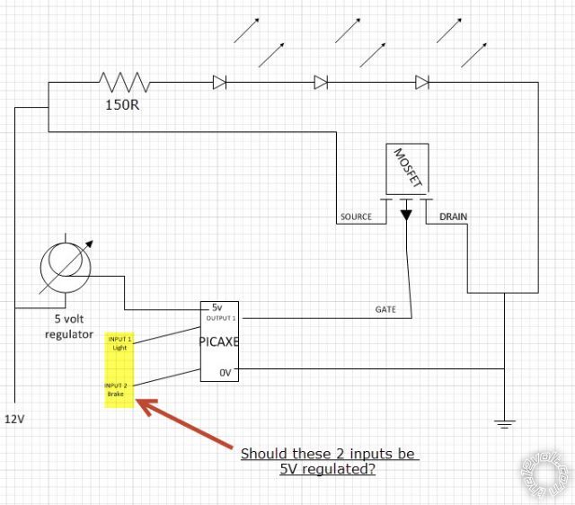
Date Posted: August 08, 2012 at 10:15 PM
-------------
AJM
Posted By: corrollaman
Date Posted: August 08, 2012 at 10:30 PM
You wrote:"Input resistance values later, though the others like 150R series LED resistors, and the MOSFET resistors look fine."
I used a resistor divider calculator, and based the values off of what I already have in hand(470R-which were purchased pre.. You)
So for the tail light I have a 470-R1 and a 150-R2.. giving me a 2.9v-3.4v range, based on 12v-14.4v fluctuation.. I then used 470-R1 and 200-R2 for the brake.. providing 3.7v-4.52v...based on 12v-14.4v input...
I really kicked myself on the last drawing after mentioning the cap.. lol
Good Morning, btw :)
-------------
AJM
Posted By: corrollaman
Date Posted: August 18, 2012 at 10:02 PM
-------------
AJM
Posted By: oldspark
Date Posted: August 19, 2012 at 5:25 AM
I'm concerned by its 200 mOhm "ON" resistance at 6A, 5V - it seems high...
Let's see, 6A x 0.2R => a 1.2V drop (at 6A). That could be okay else factored in to your resistor values.
But you might be running a much lower current, hence a lower voltage drop...
Assume 10 strings of 20mA LEDs => 2A total.
2A x 0.2R = 0.4V drop. Essentially negligible. Mind you, that assumes a 0.2R (200mR) ON resistance - I suspect it might be higher at lower currents. But it should still be ok.
BTW - the 6A @5V means with a 5V Vgs and 6A through D to D (aka Ids). The 5V Vgs should be close to your "on" voltage - ie, the PIC etc off a 5.0V supply less a bit of "output" voltage drop (which I think is only ~0.2V etc if that, though maybe 0.5V).
Remember to check if 6 LEDS per string (as per your last fig) is ok. That might be too many depending on the actual LED voltage (ie, 1.7V, 2.0V. 2.2V etc @ 20mA) and the FET and resistor drop, and the range of vehicle voltage.
However the normal design would be based on (say) 14.4V and then any "under-voltage" merely tolerated as a dimmer output. But as you might have seen, LED brightness does not depend much on the voltage.
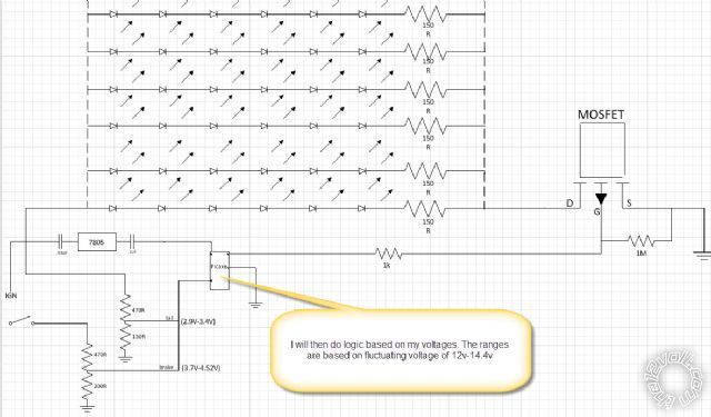
Posted By: corrollaman
Date Posted: August 20, 2012 at 8:21 AM
Good Evening!... or maybe Good Morning.. depending on when you catch the ZZZ's.
Okay.. so I looked a bit more and found this. https://www.digikey.com/product-detail/en/IRLZ14PBF/IRLZ14PBF-ND/811728
I slept on more research trying to better understand how the MOSFET works and I think I found what will work. What do you think?
-------------
AJM
Posted By: oldspark
Date Posted: August 20, 2012 at 9:51 AM
But it should be fine as per earlier.
I think of a FET (incl. MOSFET) as a voltage of ~4-5V (Vgs) fully turning on G to S up to its rated current (ie, Igs). That's for an N-channel MOSFET (equiv to an NPN transistor) - a P-ch (equiv to a PNP tranny) requires Vg to be 4-5V BELOW S (ie, Vgs = -4 to -5V.
The important things are:
- enough Vgs to turn it fully on (or near fully on);
- that Igs handles the current
- that Igs x Vgs (ie, Watts dissipated) does not exceed its power handling. If it does, add a heatsink.
Vgs below "Vgs On" means it's not fully on, but that doesn't interest us since we are simply using it as a "switch".
(Varying the Vgs voltage on a FET is like varying the Ib or Ibe (Base current) on a transistor - it varies the current thru its "heavy" path, ie, Igs, or Ice for a transistor. IOW they can be used as amplifiers - ie, the much larger output current is proportional to the input voltage or current respectively.
Many describe a FET as being a "voltage controlled transistor" noting that a transistor is controlled by its (Base) current, though there are certain important differences (eg, a transistor output is a PN junction whereas a FET is more like a resistor - it's either an N "channel" or a P channel (it does not cross thru a P or N segment).
IMO FETs are easier to use as it's merely a voltage to its Gate (at negligible current - ie, nA or uA) whereas a transistor requires "the correct (Base) current" (typically mA).
Generally you design transistor circuits "backwards" - ie, we want 200mA output for a transistor with a minimum gain of 50, hence the base current should be 200mA/50 = 4mA.
If the resistor in series with the Base is too small, the Base current might be too high and blow the Base.
For low voltage, FETs don't care. Since their input impedance/resistance is typically Giga-Ohms, the "base" (gate) current is only nano-Amps.
But web pages can explain that better than I have.
PS - good night. It's nearly 1AM here, and under 6 hours till my alarm goes off.
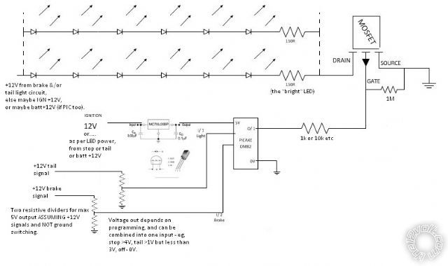
Posted By: corrollaman
Date Posted: August 22, 2012 at 10:28 AM
I understand that it will work.....but I found another one.. wondering if you think this will be more suitable... Yes or No.. hehe :-)
-------------
AJM
Posted By: oldspark
Date Posted: August 22, 2012 at 3:59 PM
Posted By: corrollaman
Date Posted: August 23, 2012 at 4:58 PM
-------------
AJM
Posted By: corrollaman
Date Posted: September 06, 2012 at 4:52 PM
I just realized that putting the two wires together coming off dividers is not going to do what i thought it would do.. what did you have in mind?
-------------
AJM
Posted By: oldspark
Date Posted: September 07, 2012 at 4:27 AM
In practice it can be [input#1 thru resistor} and [input#2 thru resistor] to PIC-input AND a resistor to +12V or +5V and a resistor to GND. Maybe a reverse-biased diode from PIC-input to its +5V rail to prevent the PIC-input voltage exceeding +5V (or 9.7V etc). (And can add similar to GND in case of -ve voltage spikes.)
Resistor size depends on input voltages and combinations (off, 1, 2, 1&2) and desired output (eg, 0V, 1V, 2V, 3V) though you usually set the programmed PIC input value/range to cover whatever voltages you end you with.
Maybe just use 2 separate inputs for now. You can change it later...