how to wire a 12v light to a led circut
Printed From: the12volt.com
Forum Name: Lights, Neon, LEDs, HIDs
Forum Discription: Under Car Lighting, Strobe Lights, Fog Lights, Headlights, HIDs, DRL, Tail Lights, Brake Lights, Dashboard Lights, WigWag, etc.
URL: https://www.the12volt.com/installbay/forum_posts.asp?tid=132189
Printed Date: May 14, 2026 at 3:08 PM
Topic: how to wire a 12v light to a led circut
Posted By: 1redvert
Subject: how to wire a 12v light to a led circut
Date Posted: September 14, 2012 at 12:03 AM
Hello, I bought a stand alone adjustable tachometer shift light off of eBay and i want to wire the shift light output to a 12volt led strip(its a led 3rd brake light)so that i can mount the shift light unit under the dash and the led strip in the window in my line of sight. the shift light unit has an led instead of a 12v bulb light that i thought it would have. my question is how do i wire it properly? do i just wire my b+ lead to the pos side of the led and ground the neg light wire or do i have to use a relay from the pos side of the led? i really am unsure because of the led in the circuit and i don't want to burn it up cause it was expensive thanks
Replies:
Posted By: oldspark
Date Posted: September 14, 2012 at 11:15 PM
If the tacho originally came with a bulb, then powering LEDs instead should be no problem.
If it originally powered a single LED (ie, 20mA), then a single LED string should be no problem.
Parallel LEDs or LED strings (ie, 40mA, 60mA, etc) might be a problem if the added current blows the LED output transistor or circuit.
A relay coil would need to draw (probably) 20mA or less - ie, LEDs or LED strings often draw less than a relay. A typical automotive relay draws 60mA to 250mA.
A transistor or MOSFET circuit could or should be used instead of a relay.
Posted By: 1redvert
Date Posted: September 15, 2012 at 3:40 AM
hi there could you recommend a transistor for me to use in this circuit? would a 500 ma 40 v be ok? i looked it up and watched a quick video about it and it looks like i would need a npn transistor. so my voltage would be positive from the led to the center of the transistor and i would power the 3rd brake light led strip by power to b+ and grounding it through the two outer prongs on the transistor right...would i need a resistor in that circuit as well?
Posted By: KPierson
Date Posted: September 15, 2012 at 2:09 PM
I would use a reed relay. Will draw around 5mA (less then an LED) and will provide enough current. The reed relay will be a bit easier to wire and no resistors will be needed.
-------------
Kevin Pierson
Posted By: oldspark
Date Posted: September 15, 2012 at 2:17 PM
Assuming the output is 5V or higher, I'd use an N-channel MOSFET. Then you only need a pull-down resistor (~1M between Gate & Source) to ensure is if off when "not on". Otherwise its similar to an NPN transistor except trannys require input-current resistors.
But yeah - assuming at least 0.7V output, thru a resistor to tranny Base; Emitter to GND, Collector to LED- thru LEDs to +12V (IGN +12V etc). Or probably whatever your web source said...
It'd be nice tho if you found out if you really needed it. Maybe the raw output is fine? [ Any specs, or did it power a bulb (no), or can you open it up (ie, maybe see what transistor drives the LED)? ]
Posted By: 1redvert
Date Posted: September 17, 2012 at 11:43 AM
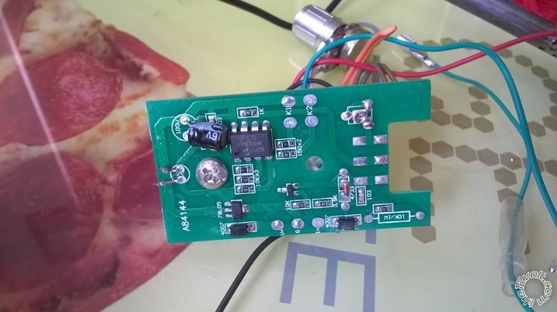
Here is the module out of the shift light and the led brake light that i would like to power with it.
https://images.thesamba.com/vw/gallery/pix/971386.jpg
https://images.thesamba.com/vw/gallery/pix/971385.jpg
https://images.thesamba.com/vw/gallery/pix/971384.jpg
Posted By: 1redvert
Date Posted: September 17, 2012 at 11:58 AM
it looks like the two transistors on the board are h945 and a 78L05
Posted By: 1redvert
Date Posted: September 17, 2012 at 12:17 PM
the led brake light draws .25 amps
Posted By: KPierson
Date Posted: September 17, 2012 at 6:47 PM
You need to be extremely careful how you approach this project. Your "expensive" shift light utilizes cheap, poorly designed hardware.
Looking at the picture of the top of the circuit board you can see the "top" lead of the LED is connected directly to 5vdc. The "bottom" lead of the LED is connected directly to the PIC 12f675 through only a resistor!
Generally you NEVER connect a device directly to a pin on a microcontroller for commercial applications. There should be a transistor in there. I've never worked with PIC's but I would assume you have less then 25mA to work with. If you can tell me the colors off of the resistor inline between the 8 pin chip and the LED I might be able to tell you the actual output. V=IR V=5 R=? I=V/R The colors on the resistor will tell you what R is.
Again, I would desolder the LED, connect a low current reed relay (usually draw 5-6mA and be done with it. Alternatively you can add a transistor but ultimately it's a bit more complicated then a simple relay.
-------------
Kevin Pierson
Posted By: 1redvert
Date Posted: September 18, 2012 at 10:37 AM
would some thing like this work to replace the the led with a solid state relay. it is 3v min and 15ma.
the resistors look like ( brown, red, 2black, brown)
https://www./itm/CRYDOM-Solid-State-Relay-SSR-MCX240D5-5A-240Vac-Load-3-15Vdc-Control-New-PCB-/290773757433?pt=LH_DefaultDomain_0&hash=item43b3776df9
thanks for the great help
Posted By: 1redvert
Date Posted: September 18, 2012 at 10:47 AM
or would this reed relay be better?
https://www./itm/0-5-Amp-SPST-Reed-Relay-at-12VDC-2160388-/150888992653?pt=LH_DefaultDomain_0&hash=item2321af4f8d
Posted By: KPierson
Date Posted: September 18, 2012 at 10:54 AM
If it is brown, red, black, black then you are looking at an R of 120 ohms. I = 5/120 = ~41mA.
However, like I mentioned before, and a quick Google search verified, the actual pin can only supply 25mA of current.
I couldn't get the link to the SSR to load. I, personally, wouldn't use an SSR as you are trying to power a low current device. SSRs are known to have a small leakage current that may cause the light to light dimly when not in use.
My recommendation would be to use a 5vdc reed relay. It has a coil that will draw minimal current and has a set of contacts that will be perfect to power your 25mA device.
https://www.radioshack.com/product/index.jsp?productid=2062478
-------------
Kevin Pierson
Posted By: KPierson
Date Posted: September 18, 2012 at 10:58 AM
1redvert wrote:
or would this reed relay be better?
https://www./itm/0-5-Amp-SPST-Reed-Relay-at-12VDC-2160388-/150888992653?pt=LH_DefaultDomain_0&hash=item2321af4f8d
You need a 5vdc reed relay, but that is very, very close. ------------- Kevin Pierson
Posted By: 1redvert
Date Posted: September 18, 2012 at 11:57 AM
sweeet that's what I've been looking for is the right one and they have that one at my local radio shack down the street. (i live in the mountains and they never have anything i need)
ok now all i have to do is replace the led with the coil of the reed switch and wire the contacts of the reed to the led strip right.
I really like electronics and would love to take a class to expand my very limited knowledge...thanks for all the help
Posted By: 1redvert
Date Posted: September 18, 2012 at 7:03 PM
the reed relay i got says 250 ohms do you think i will need to change or remove the resistor that is before the led? or just soldier it in and not worry about it?
Posted By: KPierson
Date Posted: September 18, 2012 at 7:08 PM
I'm assuming they are talking about the coil. That will give you a 20mA draw. That should be fine for your application, although it is approaching the upper limit of what the pin can safely supply. However, since it is a shift light and the actual "ON" time should be very low, it should be OK.
The resistor is in line to limit current to prevent damage to the pin. When you add the resistance of the new coil in series to the existing coil it will limit current too much. You will need to remove (or bypass) the resistor on the board for that relay to work.
-------------
Kevin Pierson
Posted By: 1redvert
Date Posted: September 18, 2012 at 8:45 PM
great thanks, thats what i was thinking as i was looking at it. I am just learning about resistors and leds because i wanted to put custom green leds in my Porsche 911 gauges. i will try and work on it later tonight and get it installed by this weekend. thanks again for all your help.
Posted By: agemax
Date Posted: October 09, 2016 at 12:06 PM
I was trawling the internet for help and i came across this thread, so i thought i would resurect it. I have just bought the same style shift light although a much updated version looking at the difference in the circuit boards....
my (probably stupid)questions are, how does this shift light work? you adjust the knob to what rpm you want the light to come on, but how does it know??
secondly, the output to power the LED (has been cut off in the pic, l/h side) is only 5v. is it possible to increase the output to 12v to power an external led that i already have, or will i just need to replace mine with 5v led's?
TIA
Posted By: KPierson
Date Posted: November 07, 2016 at 11:52 PM
Most modern shift lights measure frequency of either an injector or coil (or other pulsing signal that changes in a linear fashion with RPM). The pot is most likely creating a 0-5vdc signal that is going back to a processor that is converting the analog voltage to a digital representation and then comparing that value to the measured frequency. If the frequency value is lower than the voltage setpoint the light comes on.
You could add a transistor inline with the output to drive your 12v LED.
-------------
Kevin Pierson
|