digital led vu meter
Printed From: the12volt.comForum Name: Lights, Neon, LEDs, HIDs
Forum Discription: Under Car Lighting, Strobe Lights, Fog Lights, Headlights, HIDs, DRL, Tail Lights, Brake Lights, Dashboard Lights, WigWag, etc.
URL: https://www.the12volt.com/installbay/forum_posts.asp?tid=134095
Printed Date: March 20, 2026 at 11:54 AM
Topic: digital led vu meter
Posted By: myonus
Subject: digital led vu meter
Date Posted: April 23, 2013 at 6:40 PM
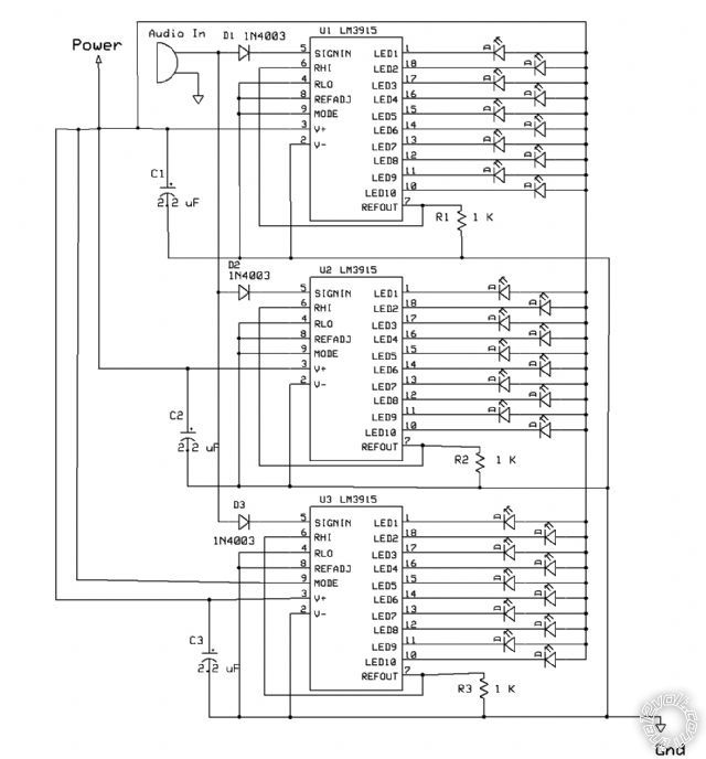
Using the LM3915 to drive a digital LED VU meter
I choose this particular circut after long debate for the following reasons:
1. simple low component. easy circut board to etch.
2. part availability and cost effectiveness, this stuff is cheap-cheap
3. the ability to daisy chain the chips with pin 9 to add additional sets of 10 LEDs; with one chip I can make 10 LEDs add two more chips and I can have 30 LEDs per side.
4. to make a conventionl 30 LED Stereo VU (60 LEDs) is not cost effective at all. Kits I have found, not even close as simple. way over priced. But they will take the super brights.
Is there a chip that can do the same as LM3915 but put out a 3.5v that will drive my super brights? (3.5 3.8v max)
or could i just modiy each pin out; put an op amp on it and still keep the end function the way I want it. (sweet and simple and super bright)
Or is this an impossible dream? And am I dreaming now? pinch-pinch--punch......nope, I'm awake.
myonus
-------------
Be not guided by morality, but rather, integrity.
Replies:
Posted By: oldspark
Date Posted: April 24, 2013 at 2:18 AM
The LM3915 outputs will handle (sink) currents up to 30mA. (A 1.5A LM317T will handle a max of 50 30mA LEDs if bar-mode used, but it will current limit if needed.)
I presume you are using additional circuitry for the conversion from linear voltage to VU?
Posted By: myonus
Date Posted: April 24, 2013 at 5:39 AM
Im not sure, I suppose I would have to, but the book im reading that was talking about it only explains the circuts diagrams. Im just trying to decypher the authors intentions.
30 LEDs in mono configuration VU meter
Written in 2000, anything isd possible. This is what I came up with. I know one thing for sure. This would look really cool sewn into the fabric of my rear seats somehow.
-------------
Be not guided by morality, but rather, integrity.
Posted By: Ween
Date Posted: April 24, 2013 at 6:09 AM
What is the range of the display you are looking for? The 3915 will do 30db. Cascading for multiple 30 db ranges requires circuitry changes.
Info from NS databook circa 1982.
Posted By: oldspark
Date Posted: April 24, 2013 at 8:09 AM
Posted By: myonus
Date Posted: April 24, 2013 at 12:23 PM
Thanks everyone for the heads up on this curious circut. Went to TI site and did a quick review of these new update march 2013 datasheets. Looks like there is quite a bit thats changed since the publication that I'm reading.
There are several points i will still need to consider, and confirmation that yes these can be cascaded together for an increased resolution of the dot display or bar display depending on how you wire pin 9.
Different additional circuts will be required for the 3916 to operate in true VU which has different scale divisions than the normal linear mode that Im used to. I think in this specific install; since its really not measureing but a peak indicator of the pre-amp, I will be just as satisfied with the less complicated linear version.
The datasheets do indicate that multiple chips can be cascaded, and a small circut can be added to increase the DB.
Scale anywhere from 1.2V to 12V independent of supply voltage. LED brightness is easily controlled with a single pot.
and finally confirmed, yet absolutely no examples of a 3 chip cascaded system in bar graph display mode. giving a total of 30 LEDs on a mono setting. Which is exactly what i want.
However i am still not convinced that this is as simple as that, as i found some older material saying that when cascading 2 chips, here ya go, example 1-4. when cascading 20 LEDs or more, its so unclear, obviously the directions:
Capacitor C1 is required if leads to the LED supply are 6< lang=JA size=1>< lang=JA face="Times New Roman" size=1>″
For bar mode, connect pin 9 to pin 3. V
20 or More LEDs: Connect pin 9 of the first drivers in the series (i.e., the one with the lowest input voltage comparison points) to pin 1 of the next higher LM3916 driver.
Continue connecting pin 9 of lower input drivers to pin 1 of higher input drivers for 30 or more LED displays.
The last LM3916 driver in the chain will have pin 9 left open.
All previous drivers should have a 20k resistor in parallel with LED #9 (pin 11 to V
I cant get past the bold areas. what I'm missing is the example. thats ok, let me try this
higherst chip 3 >>[chip 3 - pin 9] left open
next higher chip 2 >>[chip 2 - pin 9] to [chip 3 - pin 1]
lowest chip 1 >> [chip 1 - pin 9] to [chip 2 - pin 1]
Make a virtual LED out of LED # 10 by adding a resistor 20k from pin 9 to 10 and 11 to 10 - that way LED #10 is a smooth transition to the next chip.
Do the same with LED 19 20 and 21
**************oooooooooo*************
Is that what im suppose to do?? or have i been reading too much science fiction, And have certainly not pervected the flux capacitor.
OK everybody at once....... do I geta woot woot?!?!? 


or a Boot Boot?!?!? 


I really hope that somthing out of this was useful.
One thing for sure: Knowledge is power, and power is in the puddin'
----MYONUS
-------------
Be not guided by morality, but rather, integrity.
Posted By: oldspark
Date Posted: April 24, 2013 at 7:49 PM
I was going to reply that you can't use a pot to vary the brightness in bar mode, but you can. I didn't realise that pot is used to control the current limit of (each) output.
(Funny - I wonder if I knew that "back then". I used an LM2917 with 2 linear LM3914s in a (round) electronic speedo (or tachometer) with a digital center display back in the late 1970s (yep, horses drew fast carts back then). I can't recall a dimmer control which of course would have been essential, though I probably would have used a PWM to dim the digital LED segments as well. Maybe I'll check - I found the PCB drawing a while ago, tho not its circuit. Ah, yet another unfinished (35 year old) project. But these days you can buy them. Back then it was fiction, though not as real as other "impossible" things I used to do... and still seem to do!)
Posted By: myonus
Date Posted: April 24, 2013 at 9:27 PM
great find, and three was all i was interested in.
And by the way have you read the march updated datasheets for these lil fellas? its a good read/ refresher. And I agree 1 3916 and 1 3915 and a 3914 and im gonna gonna rock it like a hurricane! yeaaaaaa!
So did I get a woo hoo, or a booo hooo??????????
Thanks again, like always you simplified my week. You should get a pay pal account so the appreciatve could buy ya a Fosters for all your hard yakka,
Hoo Roo Ta, Spark
-myonus
-------------
Be not guided by morality, but rather, integrity.
Posted By: oldspark
Date Posted: April 24, 2013 at 10:07 PM
Fosters - I wonder if we even make that anymore. I recall buying some Fozzies in London to take back to some people I was staying with in the walled city of Berlin. YUK! I presume the pommie brewing water disagreed with its yeast.
A few years later I was educated by some country boys as to how bad Fosters was. They got me onto Melbourne & Victoria Bitter - the latter became the norm for drinkers a decade or 2 ago. Alas by then I was already onto others - generally small independent brewers which had great beers. In fact I learned that brewers I fell in love with (Cascade, Hahn etc) would last a year or 2 before being bought by the big multinational brewers, though Boags has lasted and is still uncorrupted. Not that beer is my drink of choice - I usually sink ciders, or gins, or vodkas, or....
Oh dear, I digressed. (I'd hate to see some mod delete this reply as well.)
Back to the LMs. Yeah - instead of recovering my old (lost) data I downloaded a few new datasheets. I may compare to my ~1978 National Linear Data Book (maybe the current control is a newer addition, or maybe I missed that entirely though it's more likely I have simply totally forgotten!).
Incidentally, that Linear and another CMOS (Logic) databook is what gave me my electronics education. I'd stare at the strange specs & timing diagrams etc and eventually they started to make sense.
I'd then figure ways of combining the various building blocks (chips or circuits) to achieve things. One of the first was an electronic Halda - an accurate odometer with 10m or 10yd resolution for car rallies. After I built it I found it was apparently impossible according to 3 electronics enthusiasts two of whom were engineers. They argued you could not do the frequency multiplication that was required. (PLLs - Phase Locked Loops - were uncommon back then - not that they were suited to the range of a speedo.) I guess it was a pity that mine worked fine, and much cheaper than the eventual electronic Halda that came out years later for ~$400 (circa 1980). That was one of three "impossible" I did at that time...
Those chips revolutionised electronics. No longer were precision or mass transistor designs needed - just chips with interfacing.
And despite PICs & uPCs, many still survive - eg, voltage regulators (especially the LM317), the 555 timer, the 4017 one-of-ten decade counter (eg, SAAB headlight dipper relays), countless Op-Amps, etc.
Some have been put to novel uses (eg, the 4017) though often I think some are inappropriate - eg, I have seen countless 555 circuits to monitor inputs for solar or battery powered stuff and the 555 takes 10mA; simple transistor or FET circuits would consume uA - even small PICc etc only consume nA - well under uA (1uA being 1/10,000th of what the 555 consumes).
Posted By: myonus
Date Posted: April 24, 2013 at 10:30 PM
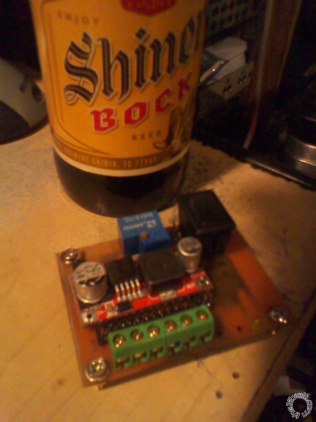
this book im reading is full od 391x. I gonna replace mt dash on my car with a digital one described n it. maybe even modify some stuff too.I just finished etching the board for my coltage regulator for my bench 12v test power supply. I sure do love this new etchant this guy makes for me in California. Its a salt crystal you mix with water 4 to 1. Anf its higghly caustic for about 30 minutes, then it turns blue and its harmless.
Anf the best thing is a can make enough with 1.5 oz of water and 1/2 oz of salts. and etch the whole side of my little power regulator. If you want to try it, I'll send you a sample bottle. Next time I order. Fantastic stuff. Not tank or exaust required, Just a plasticc ware dish, and a natural fiber painters brush. and some rubber gloves. now i can hook up my new pcb drill and get back busy on the power distibution for the car install. yep the same one, still have been pluggin away at it for weeks now, every day. Im making and fabricating almost everything from scratch.
And its been alot of fun,
Im gonna finish my Shiner Bock from good ol Shiner Texas, and hit the headboard- gnite
-myonus
-------------
Be not guided by morality, but rather, integrity.
Posted By: myonus
Date Posted: April 24, 2013 at 10:42 PM
-------------
Be not guided by morality, but rather, integrity.
Posted By: myonus
Date Posted: April 24, 2013 at 10:44 PM
oops, sorry wrong image
-------------
Be not guided by morality, but rather, integrity.
Posted By: oldspark
Date Posted: April 24, 2013 at 11:04 PM
Alas I seem to have little desire for such stuff now. I used to do a lot of automotive stuff, but now that that's "standard". LOL - I had flashers on mirrors and DRLs etc and was told they were illegal. So much for wanting speed related flash rates (for immediate & fast initial flashes for motorbikes and road racing) or third-brake lights and initial brake flashing (proportional to pressure of course!).
As to those that want to try (ha!) to smear me because of my UIBi is superior to voltage sensing stance (for battery isolators and other controls) or that oil pressure should NOT be used for electric fuel pump control (to preserve the engine - LOL!) or Continuous Audio (or Average) Power being rubbish etc, if only they realised I am typically ahead of my time (usually by 10-20 years depending on the topic) I'd have far less writing to do. Maybe I should get back into a position of authority and innovation and write specs and policies that permeate internationally...?
But enough FIGJAMming. These days I prefer to watch the intolerant and ignorant waste their 10 years of effort and expense (and engines or equipment) only to eventually apply my sort of solution. Some call that DIY. I call it reinventing the wheel... As to the watching, I think some call that "grump old men". (I call it "humor amongst the select in the know".)
I might get back into old stuff like etchants etc. With modern printers and tools - and SMD components - it'd be worthwhile for some of my stuff like my basic "universal" PIC-08M2 PCB (for use as the UIBI-3, programmable electronic ignition, smart sequential timing, etc).
Yeah - one day.
I think I'll adopt a FILO approach. If I do FIFO (first in, first out) I'm certain they will have banned ignition type vehicles. Besides, electric cars already have digital gauges with analog displays LOL, and they should not require rip-off commercial battery isolators.
Posted By: oldspark
Date Posted: April 24, 2013 at 11:05 PM
Posted By: myonus
Date Posted: April 25, 2013 at 12:07 AM
-------------
Be not guided by morality, but rather, integrity.
Posted By: oldspark
Date Posted: April 25, 2013 at 12:55 AM
A warning for first power-ups - wear safety glasses. I remember my first "back to front" 555 - the reversed supply polarity blew the center out of the chip. I felt it whiz past my cheek and eye before it hit the ceiling.
After passing that you merely need burn creams for fingers.
In extreme cases, a fire extinguisher - and a bigger can of burn cream.
It'd be interesting to know if it was a wiring issue (it usually is) or an excess power (too much LED current?) or voltage issue...
However, now being a member of said club, an "I don't know, but the new one works" is totally acceptable.
A 2nd smoke means instant promotion, but that requires a non-admission of the 2nd smoke. (Most claim that promotion status after a delay with a mere reference to some anonymous or vague project - that's assuming anyone interrogates your promotion - we do have Standards you know!)
ok, it's still morning (3:55PM Zulu)...
Posted By: myonus
Date Posted: April 25, 2013 at 2:52 AM
I would be happy to tell you exactly what happened. But after that; I can no longer uphold the high level of respect you have towards me. ..............bahhahahahah
Seriously. This is the honest tyruth. So Moderators feel free to delet this one, As I will probably never live it down.
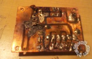
There was absolutely nothing wrong with the board, or the wiring, or the components, or the manner in witch i tested - re tested. and here we go, tested this little baby. No it was nothing except pure lack of planning. I knew for a fact I was low on solder. I knew for a fact that the only other solder I have at the moment is the solder that wa practically given to me by er- go Amazon.com seller for spending my hard earned cash in well, lets face it. "a bunch of robot parts" and to put them all togeteher, this nice brand new pound of neatly spooled solder. With the kind words on the side...........Advanced Solder Wire. And yes I knew this is the most horrific solder on the planet. Clearly manufactured by terrorists hoping we will use it on our defense electronics. Because this stuff is clearly defective.
But I was impatient, I wanted this regulator finished so i could get on with the good stuff. Well my little Radio Shack 25 watt solder iron just cant melt this stuff to a flow thats sopports the buisness end. And since I cant increase my heat, Im pullin out the big guns!! Honey! grab the kids and take the cooler, Your headed off to Grandmas house. Cause daddy is pullin out ....wait for it...............The propane plumbers torch!!! yup I smoked it. Litterally. Then after the silicon melted off the underside of the regulator, I realized once again, what happens when you mix a 10 hor day at the office, with alergy season; two benyadryl. And a couple bock beers,
A slight Momentary Lapse of Reason.
Clearly Not my best work. And Clearly Its past my bed time.
-------------
Be not guided by morality, but rather, integrity.
Posted By: oldspark
Date Posted: April 25, 2013 at 5:30 AM
I recently used my butane torch to solder an SMD PIC chip, but I plan on buying an old toaster and proper SMD solder-paste in the future...
Decades ago I bought 250g rolls of solder - one 1mm dia, the other 0.71mm dia - and they still have heaps left. (IMO 1mm is too fat for chip pins etc.)
It's important to get suitable solder - not only temperature, but also the flux/resin which must be non-corrosive to components and tracks.
I'd assume my solder has the old killer flux fumes, but hey, death is still the biggest kick of all.
And a suitable soldering iron is IMO essential. I'm lucky enough to still have my old Weller. Although I have various tips (you change tips to change the temperature, as well as the tip type), I have almost always used a "standard" fine point tip. I'll occasionally change to a hotter fat-chisel type for big wires or heat sinks etc.
But many reckon "cheap" irons are fine, and even that fancy temp-adjustables with digital temp readouts were nothing but trouble - though that was decades ago.
I'd assume a 40W iron is ok. My Weller states an output of 24V @ 2A = 48W.
Oh - be wary of static discharge. It's probably not much of an issue anymore - I think it was one of those "theoretical" hazards though modern chips and static sensitive semiconductors (eg, FETs) tend to incorporate static protection didoes. I never worried about wrist straps etc, but I would short myself and chip power pins etc (usually with the chip pins still through foil or in modern conductive foam) and the PCB to the earthed/grounded iron etc before assembly.